Analysis and Synthesis of Sequential Circuits using S-R Flip-Flops
INSTRUCTION
- Apply \(V_{CC1 }\) and \(V_{CC2}\), so that clock start button will be enabled. Apply low level voltage to ground(GND1) and (GND2).
- Next, start the clock pulse by clicking on the "Clock Start" button and after generation of some clock pulses stop the clock pulse by clicking on the"clock Stop" button. Click the button "Add to table", to insert the data.
- Now apply high voltage to S input and low voltage to R input and set "No of clock pulses" to 1. See the changes at output(Q and Q) at positive clock edge. Click the button "Add to table", to insert the data.
- Now apply high voltage to R input and low voltage to S input and start the clock pulse. See the changes at output(Q and Q) at positive clock edge. Click the button "Add to table", to insert the data.
- Next,apply low voltage to both the inputs(S and R) and see the changes at output(Q and Q) at positive clock edge. Click the button "Add to table", to insert the data.
- Next,apply high voltage to both the inputs(S and R) and start the clock pulse again.See both the outputs(Q and Q) will be zero. It is "not allowed" condition. Click the button "Add to table", to insert the data.
- Click button "Plot" to see the graphical representation of S-R flip flop.
- Note: Red symbolize as Low (L), Green symbolize as High(H).
TRUTH TABLE
| Clock | S | R | Q | \(Q_{t+1}\) | Action |
|---|
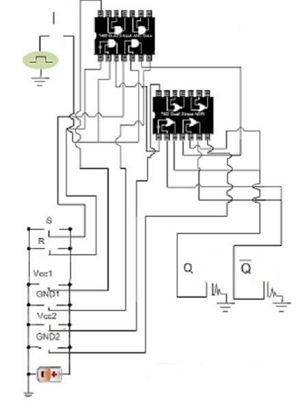
CIRCUIT DIAGRAM