


STEP 1 : Make Connections as per the instructions given below:
1. M1 of MCB - M3 of Kit
2. M2 of MCB - M4 of Kit
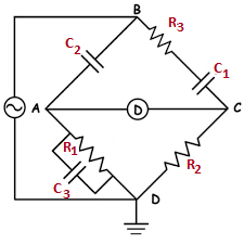
3. D1 of Digital Null Detector - D3 of Circuit Diagram
4. D2 of Digital Null Detector - D4 of Circuit Diagram
5. X1 - S1 of Capacitor
6. X2 - S2 of Capacitor
NOTE : If wire is wrongly connected, Click on node number to detach the wire.
STEP 2 : Click on "CHECK" button for checking the connections.
STEP 3 : Click on the MCB to Turn ON the supply.
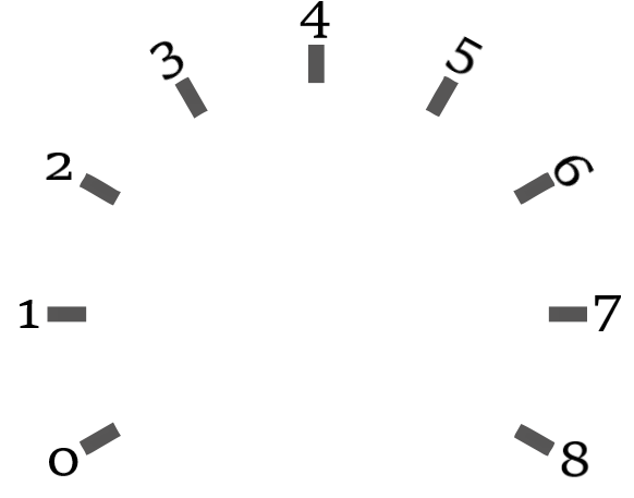
STEP 4 : Vary x10Ω knob by selecting the values from dropdown until you reach the minimum value of the digital null detector.
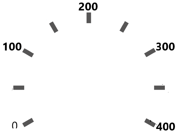
STEP 5 : Now, Vary x100Ω knob by selecting the values from dropdown until you get the minimum value of the digital null detector.
STEP 6 : Click on "ADD" button to add the readings to the Observation Table.
NOTE : If combination is wrong then select another combination & the balanced condition button becomes active after the wrong combination alert.
STEP 7 : Click on "PRINT" button to print the webpage.
STEP 8 : Click on "RESET" button to reset the webpage.
FORMULA
Find C1 (Unknown Capacitance)
C1 = R1/R2 * C2
where R1 = x10Ω + x100Ω
OBSERVATION TABLE
| S.No. | R1 (Ω) | R2 (Ω) | C2 (µF) | C1 (µF) |
|---|