-
CH1 -
mV/div V/div -
TIME(ms/div) -
Y-Shift -
X-Shift
-
CH2 -
Y-Shift -
X-Shift
D1
D2
D3
D4
+
-
A
B
C
D
T+
T-
O/p+
O/p-
C1 C2
I G O
R1
R2
L1 L2
- Click on the Component button to place components on the breadboard.
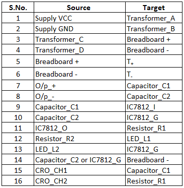
- Make connections as per the table given below.
- Click on Check Connection button. If connections are right, click on ‘OK’, then Simulation will become active.
- Observe capacitor filter and DC waveform on C.R.O by adjusting C.R.O channel CH1/CH2 and TIME knobs.
- Use X Shift and Y Shift knobs for wave shifting.
- Click on the Reset button to reset the webpage.
| S.No. | Input Voltage (V) | Capacitance (µF) | Resistance (KΩ) | Output Voltage (V) |
|---|---|---|---|---|
| 1. | 230 | 1000 | 1 | 12 |