
Pass band implementation of Amplitude shift keying, Frequency Shift Keying, Binary Phase Shift Keying: Generation and Detection
Passband Phase Shift Keying (PSK)
Theory:
Phase Shift Keying (PSK) is a digital modulation scheme in which information is transmitted by changing the phase of a carrier signal. Binary PSK (BPSK) is the simplest form of PSK, using two phases to represent binary '1' and '0'. Each input bit causes a phase shift of the carrier. The transmitted passband signal occupies a specific frequency band around the carrier frequency $f_c$, making it suitable for radio, optical, or other communication channels.
Baseband vs Passband PSK:
Baseband PSK: Binary data is mapped to voltage levels (e.g., +1 for '1' and -1 for '0')
before modulating the carrier. This signal is centered at zero frequency.
Passband PSK: The baseband signal modulates a high-frequency carrier $A_c \cos(2 \pi f_c t)$.
Binary '1' is represented by a 0° phase shift, and binary '0' by a 180° shift:
\[ x(t) = \begin{cases} A_c \cos(2 \pi f_c t), & \text{for binary 1} \\ A_c \cos(2 \pi f_c t + \pi) = -A_c \cos(2 \pi f_c t), & \text{for binary 0} \end{cases} \]
Passband PSK Transmitter:
In BPSK, the carrier phase is shifted according to the binary input. Baseband NRZ signaling is typically used:
- Binary '1': +ve voltage level (e.g., +1V)
- Binary '0': -ve voltage level (e.g., -1V)
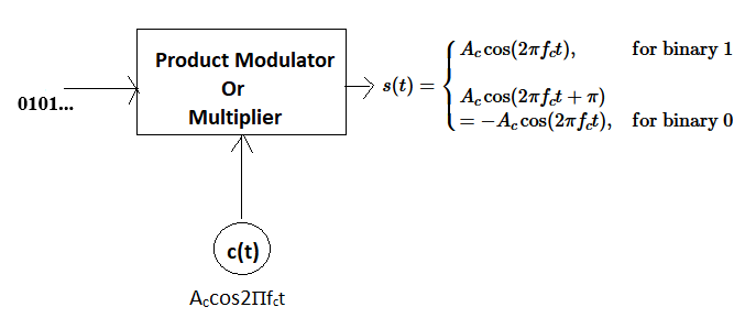
Fig 1: Passband PSK Transmitter
Passband PSK Receiver (Coherent Demodulation):
The received passband signal is multiplied by a synchronized local carrier and integrated over the bit duration $T_b$:
If '1' was transmitted:
\[
\int_0^{T_b} A_c \cos(2 \pi f_c t) \cdot A_c \cos(2 \pi f_c t) \, dt \approx \frac{A_c^2}{2} T_b
\]
If '0' was transmitted:
\[
\int_0^{T_b} (-A_c \cos(2 \pi f_c t)) \cdot A_c \cos(2 \pi f_c t) \, dt \approx -\frac{A_c^2}{2} T_b
\]
The output is then compared to a threshold $V_{th}$ to decide whether a '1' or '0' was sent.
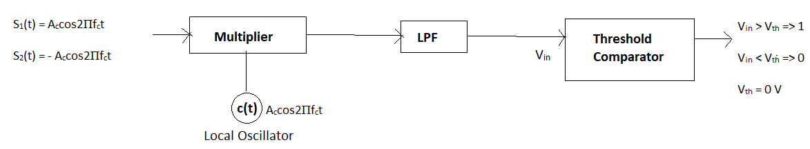
Fig 2: Coherent Passband PSK Receiver
Constellation Diagram:
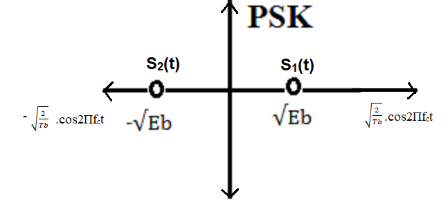
Fig 3: BPSK Constellation Diagram
Symbol energies: $E_b$ for both '1' and '0'.
Euclidean distance: $d_{12} = | \sqrt{E_b} - (-\sqrt{E_b}) | = 2 \sqrt{E_b}$
High-order PSK (QPSK, 8-PSK) transmits more bits per symbol but requires higher SNR for the same error rate.
Passband PSK in Noise Channels:
BPSK with AWGN:
\[
y(t) = x(t) + n(t)
\]
where $n(t)$ is additive white Gaussian noise. Noise can cause phase shifts, increasing bit errors. Detection reliability depends on SNR.
BPSK with Rayleigh Fading:
\[
y(t) = h(t) \cdot x(t) + n(t)
\]
$h(t)$ is the complex fading coefficient (Rayleigh distributed magnitude and uniform phase). Fading distorts amplitude and phase, increasing BER. Techniques like diversity and coding help mitigate fading effects.
Summary:
Passband PSK modulates a carrier’s phase according to digital data. Coherent demodulation is used to recover the original signal. PSK is sensitive to phase noise and fading but robust in high SNR scenarios. Higher-order PSK increases data rate but requires better SNR. Performance can be optimized using error correction, adaptive modulation, and diversity techniques.