
Pass band implementation of Amplitude shift keying, Frequency Shift Keying, Binary Phase Shift Keying: Generation and Detection
Passband Frequency Shift Keying (FSK)
Theory:
Frequency Shift Keying (FSK) is a digital modulation technique where digital information is transmitted by varying the frequency of a high-frequency carrier wave. Unlike ASK (which varies amplitude) or PSK (which varies phase), FSK encodes bits by switching between discrete carrier frequencies.
The simplest form is Binary FSK (BFSK), which uses two frequencies: the "mark" frequency \( f_1 \) for binary '1' and the "space" frequency \( f_2 \) for binary '0'. Each frequency is transmitted for a duration of one bit \( T_b \). Passband FSK signals occupy frequency bands around these carriers, making them suitable for transmission over RF links, optical channels, or other band-limited media.
Baseband vs Passband in FSK:
Baseband Signal: The input digital data represented as voltage levels (e.g., +V for binary '1', -V for binary '0'). This signal has frequency components centered around zero.
Passband Signal: The carrier is modulated in frequency according to the baseband signal: \[ s(t) = \begin{cases} A_c \cos(2 \pi f_1 t + \phi), & \text{for binary '1'} \\ A_c \cos(2 \pi f_2 t + \phi), & \text{for binary '0'} \end{cases} \] Here, \(A_c\) is the carrier amplitude, \(f_1\) and \(f_2\) are the mark and space frequencies, and \(\phi\) is the initial phase.
Passband FSK Transmitter:
A Passband FSK transmitter usually employs a Voltage-Controlled Oscillator (VCO) or a frequency synthesizer. The digital input stream modulates the carrier frequency via the VCO. The carrier amplitude remains constant, while the frequency changes according to the input bit.
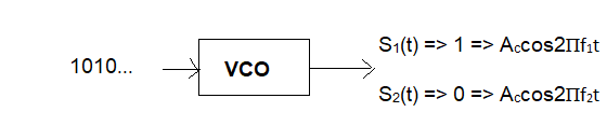
Fig 1: Passband FSK Transmitter
VCO Principle:
A Voltage-Controlled Oscillator (VCO) generates a frequency proportional to the input control voltage. For FSK, the input binary signal is converted to voltage levels that control the VCO frequency.
For an LC tank VCO with a varactor diode (capacitance \( C' \) depends on reverse-bias voltage), the frequency is:
\[
f = \frac{1}{2 \pi \sqrt{L(C + C')}}
\]
Higher control voltage (binary '1') reduces \( C' \), increasing frequency to \( f_1 \). Lower voltage (binary '0') increases \( C' \), decreasing frequency to \( f_2 \).
Passband FSK Receiver (Coherent Demodulation):
Coherent BFSK receivers require local oscillators synchronized with the transmitted mark and space frequencies. The received passband signal is split into two branches: one for detecting \( f_1 \) (mark) and one for detecting \( f_2 \) (space).
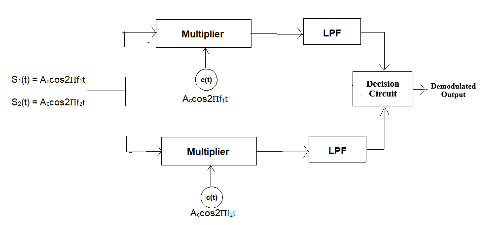
Fig 2: Coherent Passband BFSK Receiver
In each branch, the received signal is multiplied by a locally generated carrier of the corresponding frequency and phase. The product is passed through a low-pass filter (LPF), which removes the high-frequency components and leaves a DC or low-frequency signal proportional to the transmitted bit energy. These outputs are compared in a decision device:
- If the \( f_1 \) branch output > \( f_2 \) branch output, the bit is detected as '1'.
- If the \( f_2 \) branch output > \( f_1 \) branch output, the bit is detected as '0'.
Mathematical Representation:
When a binary '1' is transmitted:
\( s(t) = A \cos(2\pi f_1 t) \)
Multiplier outputs:
\(\text{Branch } f_1: A \cos(2\pi f_1 t) \cdot A \cos(2\pi f_1 t) = \frac{A^2}{2}[1 + \cos(4\pi f_1 t)]\)
LPF output: \( \frac{A^2}{2} \)
\(\text{Branch } f_2: A \cos(2\pi f_1 t) \cdot A \cos(2\pi f_2 t) = \frac{A^2}{2}[\cos 2\pi(f_1+f_2)t + \cos 2\pi(f_1-f_2)t] \)
LPF output: 0
Decision: Output is binary '1' because LPF of \( f_1 \) branch > LPF of \( f_2 \) branch.
When a binary '0' is transmitted:
\( s(t) = A \cos(2\pi f_2 t) \)
Multiplier outputs:
\(\text{Branch } f_1: A \cos(2\pi f_2 t) \cdot A \cos(2\pi f_1 t) = \frac{A^2}{2}[\cos 2\pi(f_1+f_2)t + \cos 2\pi(f_1-f_2)t]\)
LPF output: 0
\(\text{Branch } f_2: A \cos(2\pi f_2 t) \cdot A \cos(2\pi f_2 t) = \frac{A^2}{2}[1 + \cos(4\pi f_2 t)]\)
LPF output: \( \frac{A^2}{2} \)
Decision: Output is binary '0' because LPF of \( f_2 \) branch > LPF of \( f_1 \) branch.
Constellation Diagram
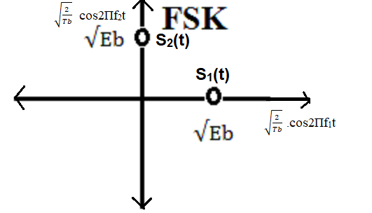
Fig 3: BFSK Constellation Diagram
The signal points lie on two orthogonal axes, separated by Euclidean distance: \[ d_{12} = \sqrt{(\sqrt{E_b})^2 + (\sqrt{E_b})^2} = \sqrt{2E_b} \] Orthogonality improves noise immunity relative to ASK. High-order FSK (M-FSK) uses M frequencies to transmit log2M bits per symbol, forming an M-dimensional constellation.
Effect of Noise and Channel Conditions
AWGN Channel:
The received signal is:
\[
y(t) = s(t) + n(t)
\]
where \( n(t) \) is additive white Gaussian noise. FSK is more robust than ASK in amplitude noise since information is frequency-based. Error probability depends on the Euclidean distance between constellation points and SNR.
Rayleigh Fading:
The received signal is:
\[
y(t) = h(t) \cdot s(t) + n(t)
\]
where \( h(t) \) is the complex fading coefficient. Fading causes random amplitude and phase variations, potentially reducing detection accuracy. Non-coherent FSK is often used in fading channels due to simpler implementation.
In summary, Passband FSK is a robust modulation scheme suitable for noisy or band-limited channels. Its constant amplitude nature makes it resilient against amplitude distortions, though its spectral efficiency is lower than PSK.