Interfacing MQ135 Sensor with Arduino
Instructions
Objective:
Learn to use the MQ135 air quality sensor to detect harmful gases (CO2, ammonia, benzene, smoke) and display air quality levels with visual indicators (RGB LED) and audio alerts (buzzer).
Steps to Perform:
- Click 'Start Simulation' to power the circuit
- Click 'Add Smoke' to introduce pollutants
- Use the slider to increase Smoke Intensity
- Watch the Buzzer Warning indicator near the slider
- Once level crosses 66%, the Buzzer will start beeping
- Click 'Stop Simulation' to reset the circuit
Key Concepts:
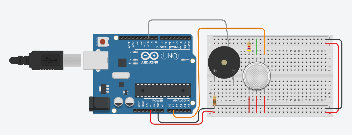
- MQ135 Sensor: Connected to Analog Pin A1. It detects smoke and gases.
- Buzzer: Connected to Digital Pin 10. Triggers when pollution is dangerous.
- Threshold Alert: Code monitors sensor and triggers alarm at > 66%.