Lesson 6: Shaping, Planing & Slotting Operations
📥 Lesson 6 DownloadTable of Contents
6.0 Shaping, Planing & Slotting operations
In the lessons 1-5, we have studied about rotary type of machine tool i.e. during the process of cutting the job rotates (as in case of lathe) and the tool is stationary. In this lesson, we are going to study about production of flat (or plane) surfaces using reciprocating type of machine tools. In these types of machines, either the tool or the workpiece will be reciprocating while the other is held stationary.Shaping, planing and slotting are process that can be defined as the process of removing metal from a surface in horizontal, vertical and inclined position to produce a flat or plane surface, slots, grooves etc. by means of a relative reciprocating motion between the tool and workpiece. (Figure-1)
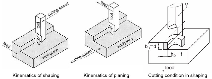 Figure 1: Process of producing a flat surface
Planing, shaping and slotting are similar operations, which differ in the kinematics of the process. Planing is a machining operation in which the primary cutting motion is performed by the workpiece and feed motion is imparted to the cutting tool. In shaping and slotting, the primary motion is performed by the tool, and feed by the workpiece. The tool reciprocateshorizontally in shaping and vertically in slotting. The cutting is intermittent in all the three processes because in the relative reciprocating motion the tool cuts only in the forwardworking (or cutting) stroke followed by the idle-return stroke. Typical components manufactured on shapers and planers are shown in Figure 2.
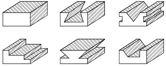 Figure 2: Typical components manufactured by shaping process
6.1 Shaper
Shaper is designed for machining flat surfaces on small sized jobs. If the size of the job is large then planing is used. In a shaper the workpiece is held stationary during cutting, while the tool reciprocates horizontally. The feed and depth of cut are, normally, provided by moving the work. Such a shaper is called a horizontal shaper. A typical horizontal shaper with its main parts is shown in Figure 3.
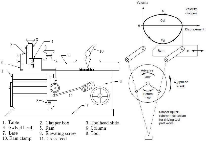 Figure 3: A horizontal shaper showing its main parts and the relationship of the crank rpm Ns to the cutting velocity V
A horizontal shaper consists of a base and frame that support a horizontal ram. The column of the shaper houses the drive mechanisms for the ram and the table. The ram is given a reciprocating motion equal to the length of the stroke. The ram carries the toolhead at its front end and travels in guideways to give straight line reciprocating motion of the tool. The toolhead holds the cutting tool. The toolhead at the end of the ram can be swiveled throughdesired angle and is provided with a slide to move the tool to provide depth of cut or manual feed motion to the tool. The tool is held in a tool holder also called tool post, which is similar to the lathe tool post. The tool holder is fixed to the ram with a clapper box, which is pivoted at the upper end such that it flips up (or lifts up) on the return stroke, lifting the tool so that thetool does not dig into the workpiece. The worktable is supported on a crossrail in the front of the column of shaper and can be moved vertically and horizontally. The table moves across the column on crossrails to give the horizontal motion to the job and moves along the column, by the elevating screw, to give the vertical motion to the job.
6.2 Shaping Operation
The workpiece is mounted on the table and length of stroke of the ram is adjusted based on the length of the workpiece. The reciprocating single point tool is mounted such that it cuts the metal when the ram (or tool) is moving out of the column till the end of stroke is reached. This is known as the cutting stroke. At the end of stroke ram stops moving forward and startsmoving back into the column. During the return of tool, the wrong side of the sharp edge (flank) comes in contact with the workpiece and cannot do the cutting. This stroke is called return stroke. At the end of return stroke, the cycle starts again.
Shapers are provided by a quick return mechanism, figure 3b, for driving the ram, which makes the return stroke is made faster, that is, ram is made to travel at faster speed during return stroke. This means per cycle of ram more time would be spent in cutting and less time in idle stroke. The cutting action in a shaper is shown in Figure 4(a).
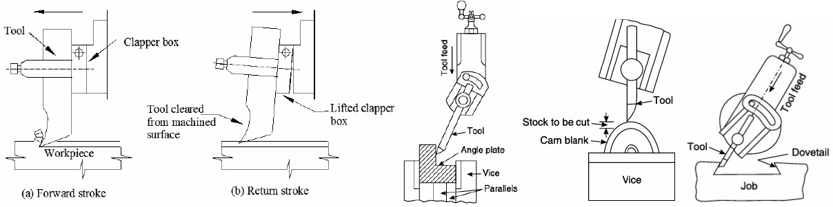 Figure 4: The cutting action and functioning of clapper box in a shaper. Also various tools positions are shown various machined surfaces to be obtained
The toolhead of a shaper or planer has a slide, which has a clapper box and a tool holder. The toolhead and the tool holder both can be swiveled independently to any desired angle for machining horizontal, vertical and inclined surfaces. The clapper box is provided to avoid the rubbing of the tool with the workpiece surface during the return stroke. The clapper box makes it possible for the tool to lift up from the workpiece surface and deflect away from the workpiece surface, as shown in Figure 4(b).
6.3 Operating conditions in shaping machine
6.3.1 Cutting Speed
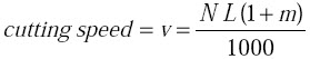
Cutting speed on shapers is defined as the average linear speed of the tool during the cutting stroke in m/min, which depends on the number of ram strokes (or ram cycles) per minute and the length of the stroke. A ratio of return stroke to cutting stroke time of 2:3 implies that the tool is working three-fifths of the time and the return stroke takes two-fifths of the time. This return-to-cutting time ratio m is a machine constant. The cutting speed v is determined by using the formula:
 (1)
(1)
where
N = the number of double strokes or cycles of the ram/min (one double or full stroke comprises of one cutting and one return stroke),
L = Length of the ram stroke, in mm,
m = return stroke time/cutting stroke time.
The ram at each end of the stroke has to come to rest (zero speed) and start moving again. It takes finite time (and distance) to attain the desired cutting speed. The distance required to attain the speed (and come to rest) is called clearance. Clearance, job length and stroke length are shown in Figure 5. The clearance is a must in shaping and allied processes unlike approach and overtravel in other metal cutting processes. Hence, for a job of length Lj a stroke length of L is used with clearance c on both sides of job, where
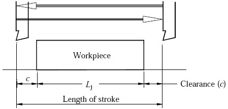 Figure 5: Length of stroke and length of workpiece
6.3.2 Feed
Feed f is the relative motion of the workpiece in a direction perpendicular to the axis of reciprocation of the ram. In shaper, feed is given to the workpiece. Feed is expressed in mm/double stroke or simply mm/stroke because no cutting is done in return stroke.
6.3.3 Depth of Cut
Depth of cut d is the thickness of the material removed in one cut, in mm. Depth of cut may be given by the toolhead slide or by lifting the table.
6.3.4 Machining time
From the cutting speed, we can find that the time required to complete one double stroke is given by
 (3)
(3)
With a feed of f mm/double stroke, number of double strokes required to machine a surface of width w will be
Hence, total time for machining the surface will be
or, in terms of ram strokes N, the time for machining surface is given by
6.3.5 Material Removal Rate
Material removal rate (MRR) in a shaping machine is given by the formula
where d is depth of cut in mm; f in mm/stroke; N in strokes/min; and L is length of stroke in mm.
6.4 Planer
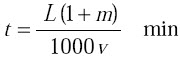
The planer (Figure 6) is a machine tool produces flat surfaces in horizontal, vertical or inclined surfaces. In planers the workpiece reciprocates past one or more stationary single point cutting tools. Planers are meant for machining large size workpieces, which cannot be machined by shaping machines. In addition to machining large parts, it is also possible tomount many small parts in line on the table of planer and machine them simultaneously. Planer consists of a large bed on which a table slides back and forth. Two vertical housings are located near the center of the bed. The horizontal crossrail is supported on the vertical housings. Both the crossrails and each of the housings are equipped with guideways so thatsliding motion may be obtained in both the vertical and horizontal directions. Since the crossrail is supported at both the ends this type of planer is rigid in construction. This permits double housing planers to take heavy cuts. In most cases, two toolheads are mounted on thehorizontal crossrail and one on each of the vertical housings. Toolheads may be swiveled so that angular cuts can be made. The tools can be fed in the workpiece manually or operated by power.
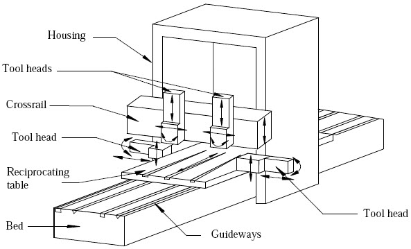
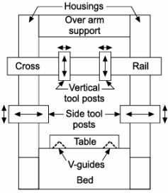 Figure 6: A double housing planer
6.5 Planing Operation
The workpiece is clamped onto a planer table with the help of special bolts that fit in the Tslots of the table, and provide a means for positioning and securely holding the workpiece. he table rides over V-grooves on the bed of the planer and is accurately guided as it travels back and forth. Cutting tools are securely held in toolheads mounted on the housing and canbe moved vertically or horizontally from side to side. The toolheads are also mounted on a horizontal cross rail that can be moved up and down. Use of multiple toolheads permits simultaneous machining of more than one surface of the workpiece and increases productivity.
6.6 Operating conditions in planers
6.6.1 Cutting speed: Similar to a shaper, the cutting speed in planing is the average linear speed of the table during the cutting stroke in m/min because in planers the tablereciprocates. Formula for calculating the cutting speed is the same as that used in case of shaping machines except that N refers to the table strokes per minute and L is length of table stroke.
6.6.2 Feed: The feed in a planing machine is the distance the tool travels at the beginning of each cutting stroke and is expressed in mm/double stroke.
6.6.3 Depth of cut: It is the thickness of metal removed in one cut, and is measured by the perpendicular distance between the machined and non-machined surfaces and is expressed in mm.
The machining time and MRR in planing operations can be calculated by using the formula given by Equations (5), (6) and (7), with changed meanings of terminology discussed. If multipletools cut a workpiece simultaneously, the total cutting time will not cumulate but MRR of each tool should be added to get total MRR.
6.7 Size of shaper and planer
The size of the shaper or planer is specified by the maximum length of the stroke. Because the maximum length of the stroke determines the maximum size (length) of the surface, which can be, machined on the shaper or planer. The normal maximum stroke length of shaper is 800 mm.
For planers, the size is also specified by the size of the largest rectangular solid that can be machined on the planer. The width of the largest solid is limited by the distance between the two housings and the maximum height is determined by the distance between top of the table and the cross rail in its uppermost position.
6.8 Difference between shaper and planer
Shapers and planers are meant for producing flat surfaces and there is overlap in their application. They differ greatly in construction and in the method of operation. Following are the main differences between shaper and planer.
- In a planer, the workpiece is mounted on table, which reciprocates while the tool is held stationary. In a shaper, the tool reciprocates and the workpiece is stationary.
- Planers are machines designed for holding big workpieces, which are too big for a shaper. Many small workpieces can be machined on a planer by clamping them together on the planer table, whereas shapers are intended for processing small workpieces one by one.
- Cutting and return speed of a planer are almost uniform throughout the stroke. But, in the shaping machine the speed varies throughout the length of the stroke.
- Planers are heavier, rigid, larger and costlier compared to shaper.
- Planers are used for mass production of small size components whereas shapers are used for batch or job shop production.
6.9 Slotting Machine
Slotting machine (slotter) (Figure 7) is like a vertical shaping machine. Slotting machine is usually used for cutting internal flat surfaces such as keyways in the holes of pulleys, gears etc. It can also be used for machining small internal cylindrical surfaces.
 Figure 7: Slotting machine and a slot produced by slotting machine
The slotting machine consists of a bed, which is rigidly built to take up all the cutting forces, a vertical column whose front face has guide ways for the reciprocatory ram. The workpiece is mounted over the table, which can be moved in horizontal plane by two perpendicular cross slides. The ram supports toolhead to which tool is attached. Machining of the workpiece inslotting machine is very much similar to that of shaping machine except for the difference that the tool reciprocates in vertical direction. By combining cross, longitudinal and rotary feed movements of the table even complex contours can be machined. The size and operating conditions of the slotting machine is defined in the same way as that of shaping and planing machines.
Example 1: Find the machining time required for maching the surface 600 x 800 mm, on a shaping machine. Assume, cutting speed as 8 m/min. The return to cutting time ratio is 1:4, and the feed is 2 mm/double stroke. The clearance at each end is 70 mm.
Solution:
Given data:
f = 2 mm/stroke, and c = 70 mm.
Given clearance at each end is 75 mm; hence, length of stroke will be, from Equation (2)
Substituting all the values in Equation (5), we get
= 46.25 minutes
Note that in the above computation of machining time on shaper it is assumed that the shaper can operate at any desired number of strokes per minute, even fractional values. On actual shapers, normally, only finite and integer values of strokes per minute will be available. In such a situation, we should first calculate the required strokes per minute according to specified maximum cutting speed and than use the nearest (lower) strokes per minute available to compute machining time. This is illustrated in next example.
Example 2: Estimate the time required to machine a cast iron surface 250 mm long and 150 mm wide on a shaper with cutting-to-return ratio of 3/2. Use a cutting speed of 21 m/min, a feed of 2 mm/stroke and a clearance of 25 mm. The available ram strokes on the shaper are: 28, 40, 60 and 90 strokes/min. Also, determine MRR assuming depth of cut as 4 mm.
Solution:
Given data:
c = 25 mm, v = 21 m/min, d = 4 mm
The cutting-to-return ratio of 3/2 gives m = 2/3
Given clearance is 25 mm, hence,
We know that (Equation (1))
From the above equation, we find number of double strokes N per minute required as
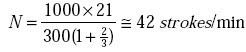
Nearest available ram strokes is 40 strokes/min. Since calculated value is more than 40, this is chosen. Normally, we should not exceed the specified cutting speed, as it will affect the tool life adversely. Hence, select N = 40 strokes/min.
With a chosen value of N, we cannot use Equation (5) for time calculation. Hence, substituting all the values in Equation (6), we get
= 1.88 minutes
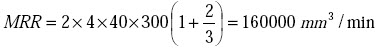
From Equation (7), we calculate the MRR as
Example 3: It is required to machine a keyway on 1000 parts as shown in Figure 8 by using shaping machine. Calculate the total machining cost. Use the following data.
Cutting speed = 8 m/min,
Return to cutting time ratio as 1:2,
Feed = 3 mm/double stroke,
Clearance at each end = 20 mm,
Maximum depth of cut = 2 mm,
Machining cost = Rs. 500/hr.
Neglect time for setup, moving, waiting and material handling.
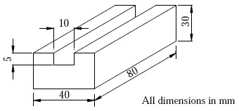 Figure 8: Figure for example 3
Solution:
Given Lj = 80 mm, c = 20 mm, w = 10 mm, v = 8 m/min,
Length of stroke = L = 80 + 2 x 20 = 120 mm.
Time required for shaping, T = L x w (1 + m) / (1000 x v x f)
=120 x 10 x (1 + 0.5) / (1000 x 8 x 3)
= 0.075 minute
It is given that maximum depth of cut possible is 2 mm. Depth of keyway is 5 mm.
Hence, total number of passes required will be 3.
Hence, time for one workpiece = 0.075 x 3 = 0.225 min.
Time for manufacturing 1000 workpiece = 0.225 x 1000 = 225 min.
Cost of machining = (500 x 225)/60 = Rs. 1875/-
REVIEW QUESTIONS
- What type of surfaces can be produced on shaper and planer?
- How is the feed obtained on a shaper? On a planer? And on a Slotter?
- For what type of work vertical shapers are used.
- Would you recommend the use of carbide tools on shapers or planers? Justify your answer.
- While machining inclined surface on a shaping machine, what happens if the clapper box is swiveled in the direction of workpiece?
- Is it true that tools used in shaper, planer and slotter be more tough as compared to lathe tools? If so why?
- It is required to do the mass production of small size flat workpieces. Suggest a suitable machine tool and justify your answer.
- What is unique about planing machine when compared to shaping machine?
- Explain how T-slots are machined?
- What is the purpose of employing approach and overtravel distance in shaping and planing operations?
- Is it possible to give feed to the table in vertical direction in shaping machine? Justify your answer.
- Can we use shapers and planers for mass production? Justify your answer.
- Explain why it is difficult to produce curved surfaces using shaping machine.
- What advantages a double housing planers have when compared to open housing planers.
- What are the differences in planing and shaping operations and their applications?
- How do you specify the size of a shaping, planing and slotting machines?
- Can we use turning tool for carrying out operations on shaping and planning machines?
- In a shaper work, the length of the stroke is 200 mm, the number of double strokes/min is 30 and the ratio of return time to cutting time is 2:3. Find the cutting speed.
[Ans.: 10 m/min]