Lesson 4: Operations on Lathe
📥 Lesson 4 DownloadTable of Contents
4.1 Operations on Lathe
Though lathe is used for producing cylindrical jobs, with special accessories and attachments, it can be used for machining of non-cylindrical jobs. The different operations that can be done on cylindrical job include turning, facing, knurling,grooving, form turning, parting, chamfering, eccentric turning, taper turning, taper turning and drilling. These operations are described briefly in the following sections.
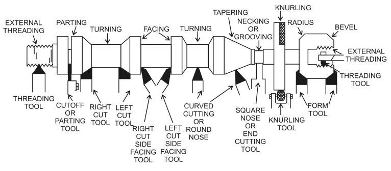 Figure 1: Various operations that can be performed on lathe
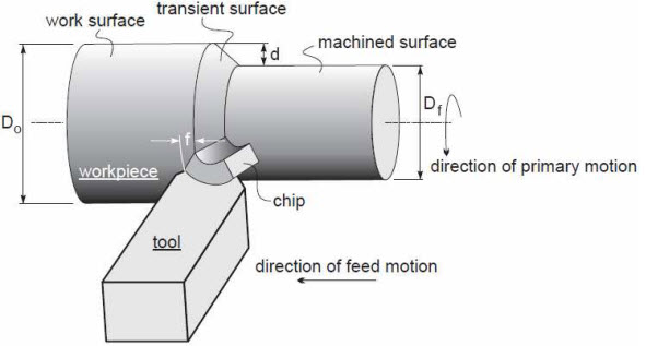
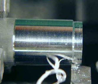
4.1.1 Turning
Turning is a machining process to produce parts round in shape by a single point tool on lathes. The tool is fed either linearly in the direction parallel or perpendicular to the axis of rotation of the workpiece. The primary motion of cutting in turning is therotation of the workpiece, and the secondary motion of cutting is the feed motion. The operation in Figure-1 is the turning operation. This operation is used to reduce the diameter of a part to a desired dimension for the desired length of job. The resultingmachined surface is cylindrical. The reduction in diameter of the job depends upon the depth of cut chosen. For example, if the depth of cut is 2 mm it will reduce the job diameter by 4 mm. The tool used for the turning operation is called turning tool.
4.1.2 Facing
Facing is the operation of machining the end or face of the job. Facing is used for reducing the length of the workpiece by machining or cutting the end face of workpiece. Facing operation is carried out by using a turning tool. The operationinvolves feeding the tool perpendicular to the axis of rotation of the workpiece from outer surface to centre. Note that in case of facing operation, the length of tool travel is equal to half the diameter of the job. The depth of cut is along the axis of the job.The facing operation is shown in Figure 3. Facing produces a flat surface.
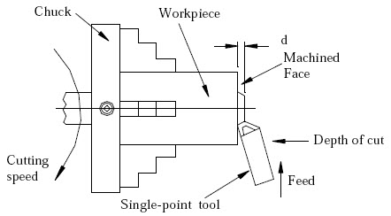 Figure 3: Facing operation
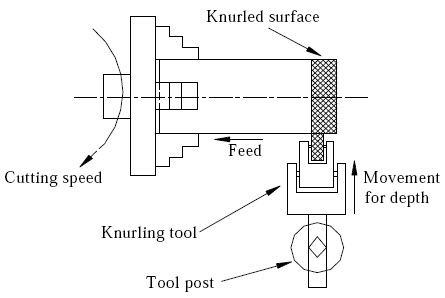
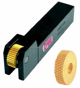
4.1.3 Knurling
This is not a machining operation at all, because it does not involve material removal. Instead, it is a metal forming operation used to produce a regular crosshatched pattern in the work surface. It is done on certain components for effective gripping toprevent it from slipping while handling it, example is thumbscrews, etc. The knurling process is shown in Figure 3. The knurling tool consists of a set of hardened steel rollers in a holder with the teeth cut on their surface in a definitepattern. The tool is held rigidly on the tool post and the rollers are pressed against the revolving workpiece to squeeze the metal against the multiple edges. The speed used during knurling should be very low and plenty of lubricant should be used.
4.1.4 Grooving
Grooving or groove cutting is the process of producing a narrow groove on the surface of a cylindrical job. The diameter of the workpiece is reduced slightly from the surface over a narrow width. The process of grooving is shown in Figure 5. The job isrevolved at slow speed and a grooving tool is fed straight into the work by rotating the cross slide screw. Note that this is the depth of cut given to the tool. There is no feed in the grooving operation.
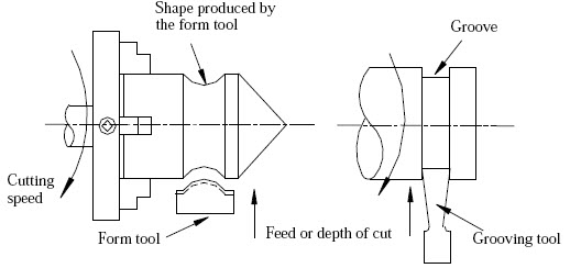 Figure 5: Grooving operations
Depending on the shape of the tool, it is possible to have square, round, beveled or any other shape grooves. In grooving operation, the shape of the tool is reproduced on the workpiece; hence, this process is also known as form turning operation.
4.1.5 Parting
As the name itself indicates, parting is the operation of cutting a workpiece into two.The operation is carried out with a tool called parting tool. The parting operation is shown in Figure 6. For parting operations, the workpiece is rotated at a low speed and the parting tool is fed in a direction normal to the axis of rotation of the job. Ample amount of feed should be employed to provide a continuous chip. If slow feed is used, the tool will not cut continuously but will ride on the surface for a revolution ortwo, and then bite in suddenly. This phenomenon is known as hogging, and is undesirable. Since, high feed rates are used, to compensate for the heat generated during the operation an abundant supply of coolant should be used.
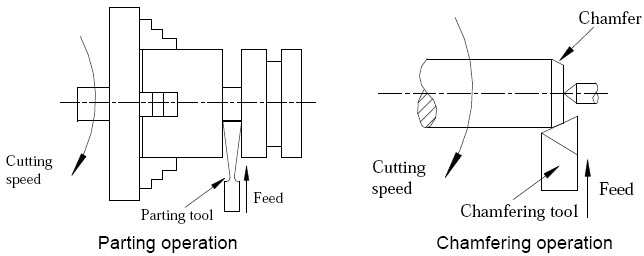 Figure: 6
4.1.6 Chamfering
Chamfering is the operation of beveling the sharp ends of a workpiece to avoid any injuries to the persons using the finished product. Chamfering is similar to form turning and is done with a chamfering toolthat has its cutting edge at the desired chamfer angle, usually 45o. Chamfer is provided for better look, to enable nut to start freely on threaded workpiece, to remove burrs as well as to protect the end of the workpiece from being damaged.
4.1.7 Eccentric Turning
If the turning operation is carried out at certain distance away from the centre of the workpiece, it is called eccentric turning. Figure 7 shows the turning of a typical component, which is eccentric. For eccentric turning operation, job is held in a four-jaw chuck.
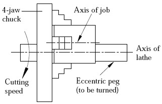 Figure 7: Eccentric turning
4.1.8 Taper Turning
A tapered job is one whose diameter decreases or increases gradually so that it assumes a conical shape. A tapered job is shown in Figure 8. Given major and minodiameters of the taper and its length, taper angle can be found. From the geometry of the figure 8 the taper angle α can be found by using the simple geometric relationship:
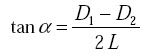
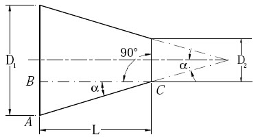 Figure 8: A tapered job showing taper angle
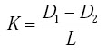
where α is angle of taper, D1 is larger diameter in mm; D2 is smaller diameter in mm, and L is length of taper in mm. The conicity K of a taper is defined as:
Accurate external tapers can be machined on a lathe by several methods viz.
1. Using a form tool,
2. Swivelling compound rest,
3. Off-Set Tail Stock, and
4. Simultaneous longitudinal and cross feeds.
4.1.8.1 Taper turning using a form tool
The form tool has a straight cutting edge set at the desired taper angle. Form tool is a replica of the taper to be produced i.e. the angle between the straight cutting edge and the rotational axis of the job equals taper angel a or one half the included angle of the taper. The tool is fed against arotating job. The shape of the tool is reproduced on the workpiece. This method is limited only for short length tapers. Figure 9 shows taper turning using a form tool.
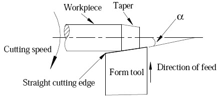 Figure 9: Taper production using form tool
4.1.8.2 Taper turning by swivelling the compound rest
The compound rest has a circular base graduated in degrees, which can be swivelled at any angle. While turning a taper, the base of compound rest is swivelled through an angle equal to taper angle. The tool is then fed by hand. This method can be used for producing short and steep tapers. Figure 10 shows the taper turning by swivelling the compound rest.
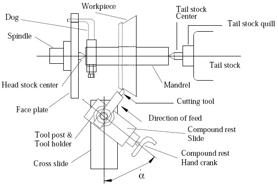 Figure 10: Taper production by swiveling the compound rest
4.1.8.3 Off-Set Tail Stock
In this method the normal rotating part of the lathe still drives the workpiece (mounted between centres), but the centre at the tailstock is offset towards/away from the cutting tool. Then, as the cutting tool passes over, thepart is cut in a conical shape. This method is limited to small tapers over long lengths. The tailstock offset h is defined by:
where, L is the length of workpiece, and α is the half of the taper angle.
h = [(D-d)/2]*(L/l)
Where, D is major diameter, d is minor diameter, L is total length of job, l is tapered length of job.
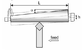 Figure 10(a) : taper turning by offsetting tailstock
4.1.9 Drilling
Drilling is the operation of production of holes in a workpiece. Figure 11 shows how drilling operation is performed on a lathe.
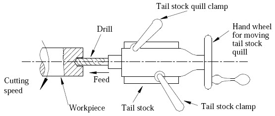 Figure 11: Drilling operation on a lathe
While doing the drilling operation on a lathe, the workpiece is held in a chuck or on a faceplate. The drill (the cutting tool) is held in the tailstock and is positioned near the workpiece by moving the tailstock along the guideways. The tool is fed against theworkpiece (the feed motion) by rotating the handle of the tailstock in clockwise direction,. Once the hole is drilled, the tool is withdrawn by rotating the tailstock handle in the anti clockwise direction. It should be noted that in drilling on lathe the job is rotating while the tool remains stationary.
4.1.10 Thread Cutting
Thread cutting is the operation of producing a helical groove of specific shape on a cylindrical surface. Figure 12 shows the setup of a lathe for thread cutting. Thread cutting operation is done using a single point tool called thread cutting tool. Threads are cut using lathes by advancing the cutting tool at a feed exactly equal to thethread pitch. For producing threads of pitch p mm, the tool must travel a distance equal to p mm as the workpiece makes one complete rotation. The single-point cutting tool cuts in a helical band, which is actually a thread. In FPS system, threads are specified as threads per inch or TPI. For example, if a workpiece is having fourthreads per inch then the pitch of the thread is equal to ¼ inch. The definite relative rotary and linear motion between the workpiece and tool is achieved by locking or engaging the carriage with the lead screw through a screw and nut mechanism and fixing a gear ratio between the head stock spindle and lead screw. This is done by using change gear mechanism or a gearbox between the spindle and lead screw.
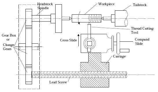 Figure 12: Lathe set up for thread cutting operation
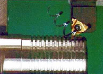 Figure 12a: Thread cutting operation
To cut the threads the tool is brought to the start of the workpiece and a small depth of cut is given to the tool using cross slide. The carriage is engaged with the lead screw, the cut is made on the entire surface and at the end of workpiece, carriage isdisengaged. The tool is pulled out of the job and brought back to starting position. The process is repeated until the full depth threads are obtained. The helix is restarted at the same location each time if multiple passes are required to cut theentire depth of thread. The tool point must be ground so that it has the same profile as the thread to be cut.
4.2 Process Sequence
The process sequence implies the order in which the operations are to be carried out to complete the machining of a job. This is like, to wear the shoes, you have to wear the socks first. This sequence to be adopted depends upon the operations to be performed on theworkpiece. This is illustrated with an example. Imagine that you are asked to produce the component shown in Figure 13 from the stock (raw material) of size 30 mm diameter and 45 mm length.
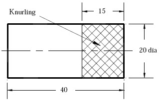 Figure 13: Component to be produced
To produce this component, one has to do turning to get desired diameter of 20 mm (reduce from 30 mm to 20 mm), do facing to reduce length from 45 mm to 40 mm and do knurling for the 15 mm length.
A possible sequence for the component could be (1) turning, (2) facing, and (3) knurling. It is also possible to produce the component by first facing, then turning and knurling in the last. Another sequence is also possible, but the knurling cannot be done first. It is obvious thatthere can exist more than one possible sequence for producing the same component. The general steps when turning external workpart hold in a chuck should follow the next sequence,
- First rough cuts are applied on all surfaces, starting with the cylindrical surfaces (largest diameters first) and then proceeding with all faces;
- Special operations such as knurling and grooving (if any) are applied;
- Diameters are finished first, then the faces.
- External threads (if any) are cut.
Example: Write the process sequence to be used for manufacturing the component shown in Figure 14 from raw material of 175 mm length and 60 mm diameter.
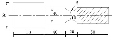 Figure 14: Figure for Example
Solution: To write the process sequence, first list the operations to be performed. The raw material is having size of 175 mm length and 60 mm diameter. The component shown in Figure-14 is having major diameter of 50 mm, step diameter of 40 mm, groove of 20 mm andthreading for a length of 50 mm. The total length of job is 160 mm. Hence, the list of operations to be carried out on the job are turning, facing, thread cutting, grooving and step turning.
A possible sequence for producing the component would be:
- Turning (reducing completely to 50 mm)
- Facing (to reduce the length to 160 mm)
- Step turning (reducing from 50 mm to 40 mm for a length of 110 mm)
- Grooving and
- Thread cutting
Here it is assumed that facing is done on only one side of the workpiece.