Lesson 2: Metal Cutting & Cutting Tool for Lathe
📥 Lesson 2 DownloadTable of Contents
2.0 Introduction
The process in which a thin layer of excess metal (chip) is removed by a wedge-shaped single-point or multipoint cutting tool with defined geometry from a work piece, through a process of extensive plastic deformation.
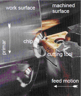
Close-up view of a turning operation in which a thin layer of metal (chip) is removed from the work surface of a rotating work piece by a cutting tool. The newly generated surface is referred to as a machined surface. Cutting process requires both primary and feed motions.
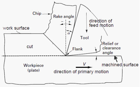
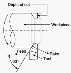
Schematics of metal cutting process showing the basic terminology. Two basic angles in cutting tool shown for plate machining with fixed tool and moving plate.
2.1 Plastic deformation in Metal cutting
The cutting itself is a process of extensive plastic deformation to form a chip that is removed afterward. The basic mechanism of chip formation is essentially the same for all machining operations. Assuming that the cutting action is continuous, we can develop so-called continuous model of cutting process shown in the figure:
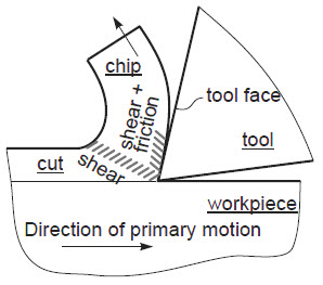
Chip formation in metal cutting is accompanied by substantial shear and frictional deformations in the shear plane and along the tool face.
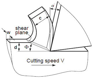
2-d cutting process, d and w are the thickness (depth) of cut and width (feed) of cut respectively, c is the chip thickness, a is the tool rake angle, and F is the shear plane angle
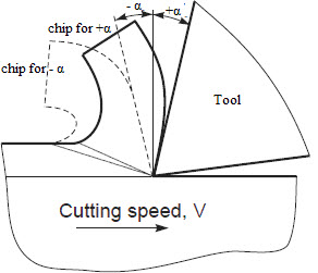
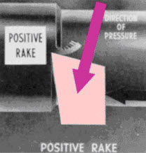
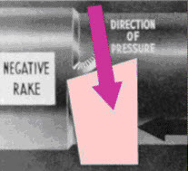
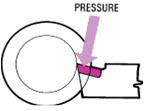
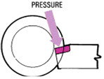
Cutting with positive and negative rake angles. Note the change in the shear plane angle and chip thickness shown by broken line.
2.2 Types of cutting
Depending on whether the stress and deformation in cutting occur in a plane (2-d case) or in the space (3-d case), we consider two principle types of cutting:
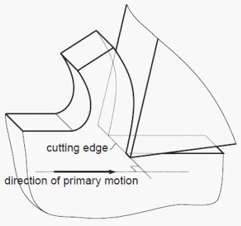
2.2.1 Orthogonal cutting
The cutting edge is straight and is set in a position that is perpendicular to the direction of primary motion. This allows us to deal with stresses and strains that act in a plane.
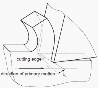
2.2.2 Oblique cutting
The cutting edge is set at an angle (the tool cutting edge inclination λs). This is the case of three-dimensional stress and strain conditions.
2.3 Types of cutting tools
Cutting tools are most important components in machining process and the efficiency of operation depends on the performance of tools. According to the number of active cutting edges engaged in cutting, we distinguish again two types of cutting:
2.3.1 Single-point cutting tool
Has only one major cutting edge. Examples: turning, shaping, boring.
 Single point cutting tool
2.3.2 Multipoint cutting tool
Has more than one major cutting edge. Examples: drilling, milling, broaching, reaming. Abrasive machining is by definition a process of multipoint cutting.
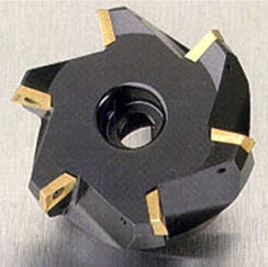 Multipoint cutting tool for milling
2.4 Cutting conditions
Each machining operation is characterized by cutting conditions, which comprises a set of three elements:
- Cutting velocity (V): the traveling velocity of the tool relative to the work piece (speed difference between the cutting tool and the surface of the work piece). It is measured in m/s or m/min.
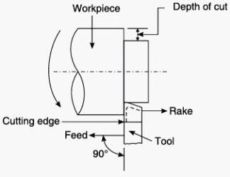
- Depth of cut (d): the axial projection of the length of the active cutting tool edge, measured in mm. In orthogonal cutting it is equal to the actual width of cut.
- Feed (f): the relative velocity of the tool at which it is advanced along the workpiece in order to process the entire surface of the work piece. In orthogonal cutting it is equal to the thickness of and is measured in mm/revolution in turning, or mm/min in milling and drilling. Feed rate units depend on the motion of the tool and workpiece; when the workpiece rotates (e.g., in turning and boring), the units are almost always distance per spindle revolution [mm/rev]). When the workpiece does not rotate (e.g., in milling), the units are typically distance per time [mm/min]).
2.5 Machinability
Machinability is a term indicating how the work material responds to the cutting process. In the most general case good machinability means that material is cut with good surface finish, long tool life, low force and power requirements, and low cost.
2.6 Cutting tool terminology
Most of the cutting tools have three angles, i.e. rake angle, clearance angle and setting angle. A general purpose hand chisel is shown in the figure below with all these three angles. These angles are provided to make the process of cutting easier in terms of reduced friction between work and the tool, easy disposal of cut material (chip), reduced cutting forces, low wear and more tool life.
The standard terminology is shown in the following figure. For single point cutting tools, the most important angles are the rake angles, end relief angle and side relief angle.
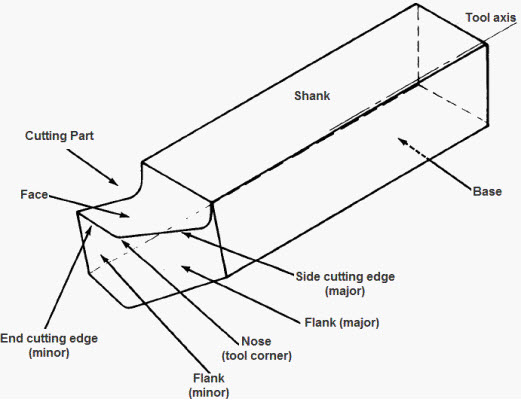 Oblique view of tool from cutting edge: Standard terminology to describe the geometry of single-point cutting tool
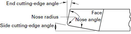 Top view
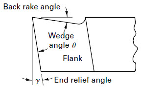
 Side view
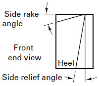
 Side shank view or front view
The actual geometry varies with the type of work to be done.
- Cutting edge: The cutting edge is the part of the tool bit that actually cuts into the work piece, located behind the nose and adjacent to the side and face.
- Shank: The shank is the main body of the tool bit. Shank is held in tool holder.
- Nose: Tip of cutting tool formed by junction of cutting edge and front face. The nose radius is the rounded end of the tool bit. Finishing of process depends on nose radius.
- Face: The face is the top surface of the tool bit upon which the chips slide as they separate from the work piece.
- Flank: The flank of the tool is the surface just below and adjacent to the cutting edge.
- Base: The base is the bottom surface of the tool bit, which usually is ground flat during tool bit manufacturing.
- Heel: The heel is the portion of the tool bit base immediately below and supporting the face.
- Point: End of tool that has been ground for cutting purposes.
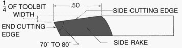 Figure 6: Sample shape and dimensions of lathe single point cutting tool
Side rake angle: If viewed behind the tool down the length of the toolholder, it is the angle formed by the face of the tool and the centerline of the workpiece. A positive side rake angle tilts the tool face down toward the floor, and a negative angle tilts the face up and toward the workpiece.
Negative angle: If the cutting edge of the tool is ahead of the perpendicular, the angle is, by definition, negative.
Positive angle: If the leading edge of the blade is behind the perpendicular, the angle is by definition, positive.
 Positive side rake angle
 Negative side rake angle
 Positive back rake angle (top face slopes downward away from point)
 Negative back rake angle (top face slopes upward away from point)
Back rake angle: If viewed from the side facing the end of the workpiece, it is the angle formed by the face of the tool and a line parallel to the floor. A positive back rake angle tilts the tool face back, and a negative angle tilts it forward and up.
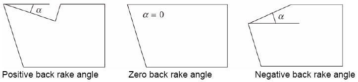 Figure: 8
- End cutting edge angle: If viewed from above looking down on the cutting tool, it is the angle formed by the end flank of the tool and a line parallel to the workpiece centerline. Increasing the end cutting edge angle tilts the far end of the cutting edge away from the workpiece.
- End relief angle: If viewed from the side facing the end of the workpiece, it is the angle formed by the end flank of the tool and a vertical line down to the floor. Increasing the end relief angle tilts the end flank away from the workpiece.
- Side cutting edge angle: If viewed from above looking down on the cutting tool, it is the angle formed by the side flank of the tool and a line perpendicular to the workpiece centerline. A positive side cutting edge angle moves the side flank into the cut, and a negative angle moves the side flank out of the cut.
- Side relief angle: If viewed behind the tool down the length of the toolholder, it is the angle formed by the side flank of the tool and a vertical line down to the floor. Increasing the side relief angle tilts the side flank away from the workpiece. Permits side of tool to advance into work.
- Angle of keenness: Formed by side rake and side clearance.
Functions of rake angle
- The strength of the cutting tool depends on rake angle.
- Allows the chip being cut to flow out.
- Changing the rake changes the power used in cutting and the heat generated.
- Positive (large) rake may be used for soft ductile materials. Positive rake angles improve the cutting operation with regard to forces and deflection; however, a high positive rake angle may result in early failure of the cutting edge. Positive rake angles are generally used in lower-strength materials. It reduces friction and heat. Allows chip to flow freely along chip tool interface.
- Negative (or small) rake may be used for higher-strength, hard, brittle materials. It has more cross sectional area for resisting the cutting forces. Strength of the tool is maximum when rake angle is negative.
- Back rake usually controls the direction of chip flow and is of less importance than the side rake.
Functions of side cutting angle
- The side cutting-edge angle influences the length of chip contact and the true feed.
- Small end cutting-edge angles may create excessive force normal to the workpiece.
- The greater the angle, the more tool deflection and weakens the tool point.
- The smaller the angle, the bigger the chip and more the tool will wear.
Functions of clearance angle
- The purpose of relief angles is to avoid interference and rubbing between the workpiece and tool flank surfaces, i.e. it ensures only the cutting edge of the tool touches the work
- Too much clearance angle weakens the tool and causes chatter
- In general, they should be small for high-strength materials and larger for softer materials.
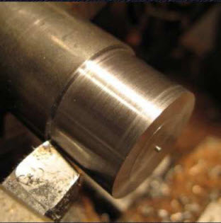 Figure 9: Cutting tool in action. Effect of clearance and relief angles can be observed
Functions of nose radius
- The purpose of the nose radius is to give a smooth surface finish and to obtain longer tool life by increasing the strength of the cutting edge.
- A large nose radius gives a stronger tool and may be used for roughing cuts; however, large radii may lead to tool chatter and more power requirement.
- The nose radius should be tangent to the cutting-edge angles.
- A small nose radius reduces forces and is therefore preferred on thin or slender workpieces.
Factors for choosing type and rake angle for cutting tool
- Hardness of metal to be cut
- Type of cutting operation, i.e. continuous or interrupted
- Material and shape of cutting tool
- Strength of cutting edge
2.7 Shapes of standard cutting tool
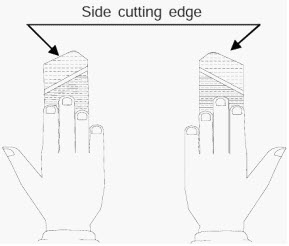
With respect to direction of feed, single point cutting tools may be classified as either left hand or right hand, depending on their cutting edge on the specified side and will cut when moved from left to right or right to left.
In right hand cutting tool the side cutting edge is on the side of the thumb when the right hand is placed on the tool with the hand fingers pointing towards the tool nose. Right hand tool cuts from right to left.
In left hand cutting tool the side cutting edge is on the thumb side when the left hand is placed on the tool. Left hand cutting tools are designed to cut best when traveling from left to right.
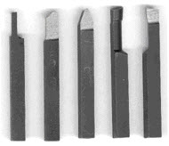 Lathe tools are usually shaped by the machinist using a grinding wheel
Figure: 10
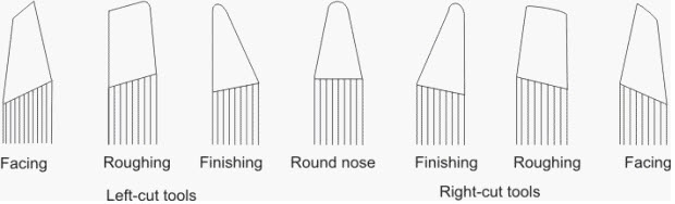
Facing tools are ground to provide clearance with a center.
Roughing tools have a small side relief angle to leave more material to support the cutting edge during deep cuts.
Finishing tools have a more rounded nose to provide a finer finish. They have no back or side rake to permit cutting in either direction.
2.8 Properties of Cutting Tools
A wide variety of cutting-tool materials are available. The selection of a proper material depends on such factors as the cutting operation involved, the machine to be used, the work piece material, production requirements, cost, and surface finish and accuracy desired.
Cutting tools are subjected to abrasion, high temperature and contact stresses. Therefore, major qualities (properties) required in a cutting tool are (See Table 1):
- hard
- hot hardness, ability of cutting tool to maintain sharp cutting edge even when turns red because of high heat during cutting
- resistance to mechanical impact and thermal shock,
- wear resistance, and
- chemical stability and inertness to the workpiece material being machined.
- Shaped so edge can penetrate work
2.9 Cutting tool Materials
Lathe toolbits generally made of five materials
- High-speed steel
- Cast alloys (such as stellite)
- Cemented carbides
- Ceramics
- Cermets
- More exotic finding wide use
- Borazon and polycrystalline diamond
2.10 Effect of alloying elements
Understanding the different types of tool steels requires knowledge of the role of different alloying elements. These elements are added to:
- obtain greater hardness and wear resistance,
- obtain greater impact toughness,
- impart hot hardness to the steel such that its hardness is maintained at high cutting temperatures, and
- decrease distortion and warpage during heat treating.
2.11 High speed steel (HSS) toolbits
- May contain combinations of tungsten, chromium, vanadium, molybdenum, cobalt
- Can take heavy cuts, withstand shock and maintain sharp cutting edge under red heat
- Generally two types (general purpose)
- Molybdenum-base (Group M)
- Tungsten-base (Group T)
Cobalt added if more red hardness desired
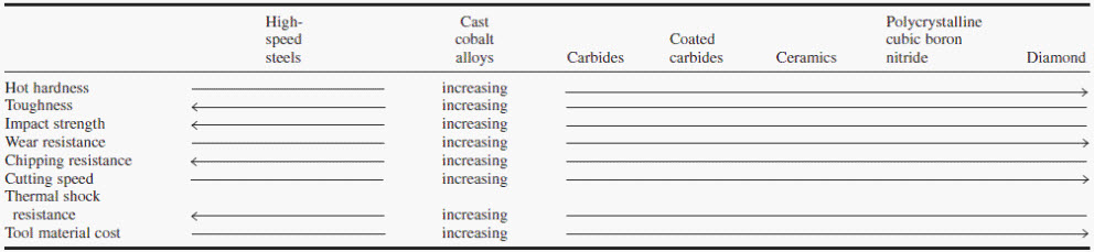 Figure 11: Characteristics of Cutting-Tool Materials
2.12 Types of wear observed in cutting tools
Crater wear: consists of a concave section on the tool face formed by the action of the chip sliding on the surface.
Flank wear: occurs on the tool flank as a result of friction between the machined surface of the workpiece and the tool flank.
Corner wear (nose wear): occurs on the tool corner. Can be considered as a part of the wear land and respectively flank wear since there is no distinguished boundary between the corner wear and flank wear land.
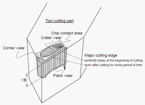 Figure 12: Types of wear observed in cutting tools
2.13 Chip Formation
There are three types of chips that are commonly produced in cutting
- discontinuous chips
- continuous chips
- continuous chips with built up edge
A discontinuous chip comes off as small chunks or particles. When we get this chip it may indicate
- brittle work material
- small or negative rake angles
- coarse feeds and low speeds
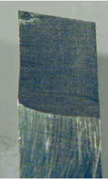
A continuous chip looks like a long ribbon with a smooth shining surface. This chip type may indicate
- ductile work materials
- large positive rake angles
- fine feeds and high speeds
Continuous chips with a built up edge still look like a long ribbon, but the surface is no longer smooth and shining.
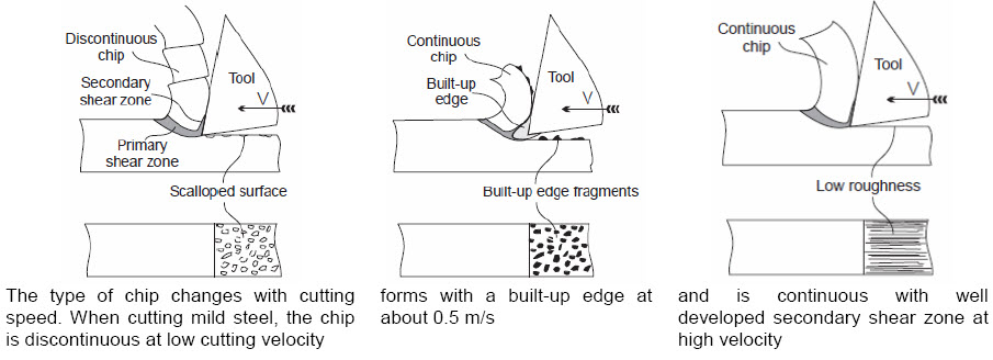 Figure: 13
Discontinuous chips are generally desired because they:
- are less dangerous for the operator
- do not cause damage to workpiece surface and machine tool
- can be easily removed from the work zone
- can be easily handled and disposed after machining.
There are three principle methods to produce the favourable discontinuous chip:
- proper selection of cutting conditions
- use of chip breakers
- change in the work material properties
2.14 Cutting Fluids
Cutting fluids, frequently referred to as lubricants or coolants, comprise those liquids and gases which are applied to the cutting zone in order to facilitate the cutting operation. A cutting fluid is used:
- to keep the tool cool and prevent it from being heated to a temperature at which the hardness and resistance to abrasion are reduced;
- to keep the workpiece cool, thus preventing it from being machined in a warped shape to inaccurate final dimensions;
- through lubrication to reduce friction and power consumption, wear on the tool, and generation of heat;
- to provide a good finish on the workpiece;
- to aid in providing a satisfactory chip formation;
- to wash away the chips (this is particularly desirable in deep-hole drilling, hacksawing, milling, and grinding); and
- to prevent corrosion of the workpiece and machine tool.
 Figure 14: Application of cutting fluid during machining
Classification of cutting fluids
Cutting fluids may be classified as follows:
(1) emulsions,
(2) oils, and
(3) solutions (semisynthetics and synthetics).