Lesson 5: Rolling Processes
📥 Lesson 5 Download- Metal Spinning
- 5.0 Introduction
- 5.1 Rolling Operation
- 5.2 Hot Rolling
- 5.3 Cold Rolling
- 5.4 Rolling Mills
- 5.4.1 Two High, Pull Over
- 5.4.2 Two High, Reversing
- 5.4.3 Three High
- 5.4.4 Four High
- 5.4.5 Continuous Mills
- 5.4.6 Planetary Rolling Mill
- 5.4.7 Universal Rolling Mill
- 5.5 Rolling Parameters
- 5.6 Thread Rolling
- 5.7 Defects in Rolled Plates and Sheets
Metal Spinning
When dies are uneconomical to make for a forming operation because of small number of parts to be made, spinning could be a solution. Metal spinning is a term used to describe the forming of metal into seamless (jointless), axisymmetric shapes by a combination of rotational motion and force. Metal spinning typically involves the forming of axisymmetric components over a rotating mandrel using rigid tools or rollers.
Figure 1 shows examples of products made from metal spinning. The range of components include:
- Bases, baskets, basins, and bowls
- Bottoms for tanks, hoppers, and kettles
- Canopies, caps, and canisters
- Housings for blowers, fans, filters, and flywheels
- Ladles, nozzles, orifices, and tank outlets
- Pails, pans, and pontoons
- Cones, covers, and cups
- Cylinders and drums
- Funnels and horns
- Domes, hemispheres, and shells
- Rings, spun tubing, and seamless shapes
- Vents, venturis, and fan wheels
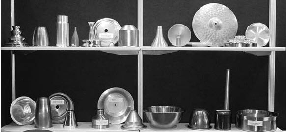
Figure 1: Various components produced by metal spinning
The equipment for metal spinning is based on lathe technology, with appropriate modifications for the components that are being formed. Typically, sheet performs flat sheet) are employed to allow relatively low forming stresses. Metal spinning can be used to cost-effectively produce single or a small number of parts out of expensive materials. In manual spinning, a circular blank of a flat sheet, or preform, is pressed against a rotating mandrel using a rigid tool. The mandrel is mounted on the lathe head stock and the live centre (tail stock) of lathe is used to hold the sheet metal in place. The spinning tool is moved either manually or hydraulically over the mandrel to form the component, as shown in Figure 2 & 3. The forming operation can be performed using several passes. Tools of different configurations can be used.
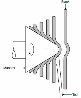
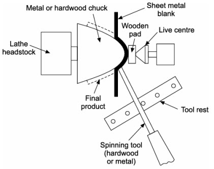
Figure 2: Metal spinning process, showing the deformation of a metal disk over a mandrel to form a cone | Figure 3: Spinning process to form sheet metal over a revolving mandrel
5.0 Introduction
The process of shaping metals and alloys into semi-finished or finished condition by passing between rolls is known as rolling. This process involves the plastic deformation of the metal in which the thickness of the metal is reduced, while the length and width are increased. There are two types of rolling process, flat and profile (shape) rolling. In flat rolling the final shape of the product is either flat sheet (typically thickness less than 3 mm, also called "strip") or plate (typically thickness more than 3 mm). In profile rolling the final product may be a round rod or other shaped bar, such as a structural section (rails for railway lines, girders for bridges (I-beam), channel, joist, 90 degree angle section, etc). Rolling is the most used metal forming process and accounts for about 90 percent of all metal products produced by metal forming. Rolling is also classified according to the temperature of the metal rolled. If the temperature of the metal is above its recrystallization temperature, then the process is termed as hot rolling. If the temperature of the metal is below its recrystallization temperature, the process is termed as cold rolling.
- Production of flat parts at high speeds
- Production of various structural shapes
- High capital investment
- Low to moderate labor cost
5.1 Rolling Operation
The process of rolling consists of passing the ingot (the piece of metal to be rolled) through two rolls rotating in opposite directions at a uniform peripheral speed. The space between the rolls is adjusted to confirm to the desired thickness of the rolled section. The rolls, thus, squeeze the ingot and as it comes out of the rolls, its thickness or cross section is reduced and its width and length are increased. The rolling process is shown in Figure 5.1.
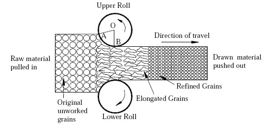
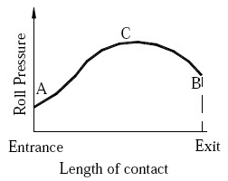
Figure 5.1 Rolling process and deformation of grains in rolling | Figure 5.2 Pressure variation in rolling
The structural changes that occur in the material during the rolling process are shown in Figure 5.1. Because of squeezing, the grains are elongated in the direction of rolling and the velocity of material at exit is higher than that at the entry. After crossing the stress-zone, grains start refining in the case of hot rolling. In cold rolling, grains retain the shape acquired by them during rolling.
The rolls are in contact with the metal for a distance AB, as shown in Figure 5.1. The angle AOB subtended at the center of the roll by the arc AB is known as angle of contact or the angle of bite. It is the friction between the surfaces of the metal and the rolls, which provides the required grip of the rolls over the metal piece to draw the latter through them. The greater is the coefficient of friction more is the possible reduction. However, energy is dissipated in overcoming friction, so increasing friction means increasing forces and more power consumption. Furthermore, high friction could damage the surface of the rolled product. We therefore have to make a compromise. For obtaining low coefficients of friction, effective lubricants are used.
The pressure distribution in rolling process is shown in Figure 5.2. The pressure distribution is not uniform throughout, but varies as shown. It is seen from the figure that it is minimum at both ends and maximum at a point C somewhere in between A-B. From point A to point C the metal moves slower than the roll and from C to B, the metal moves faster than the roll.
Roll-work contact length is reduced with a lower roll radius, and this leads to lower forces, torque, and power. The four-high rolling mill uses two smaller diameter rolls to contact the work and two backing rolls behind them. Another roll configuration that allows smaller working rolls against the work is the cluster rolling mill.
Rolling is often the first process that is used to convert material into a finished wrought product. Thick starting stock (ingot) can be rolled into blooms, billets, or slabs or these shapes can be obtained directly from continuous casting Ingot. It is the initial product obtained by the casting of molten metal. It may be of circular, square or any other convenient cross-section.
Rolling of blooms, slabs, billets, and plates is usually done at temperatures above the recrystallization temperature (hot rolling). Sheet and strip often are rolled cold in order to maintain close thickness tolerances.
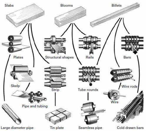
Figure 5.3: Flow chart for various flat rolling and shape rolling processes. White hot steel ingots (continuous cast products) are passed through rolls which form the plastic steel into slab, billet, bloom and semi-finished steel shapes. (Picture courtesy: Degarmo's Manufacturing Process)
| Flat rolling products at a glance | |
|---|---|
| Bloom | First breakdown of ingot (cross sectional area > 225 cm2). |
| Billet | Reduction by hot rolling (cross sectional area > 4x4 cm2). |
| Slab | Hot rolled ingot (area > 100 cm2, width = 2 x thickness). |
| Plate | Thickness > 6 mm. |
| Sheet | Thickness < 6 mm and width > 300 mm. |
| Strip | Thickness < 6 mm and width < 300 mm. |
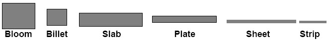
Figure 5.4: Flat Rolling Products
5.2 Hot Rolling
The distinctive mark of hot rolling is not a crystallized structure, but the simultaneous occurrence of dislocation propagation and softening processes, with or without recrystallization during rolling. The dominant mechanism depends on temperature and grain size. In general, the recrystallized structure becomes finer with lower deformation temperature and faster cooling rates and material of superior properties are obtained by controlling the finishing temperature.
- Flow stresses are low, hence forces and power requirements are relatively low.
- Ductility is high; hence large deformations can be taken (in excess of 99% reduction).
- Complex part shapes can be generated.
5.3 Cold Rolling
Cold rolling, in the everyday sense, means rolling at room temperature, although the work of deformation can raise temperatures to 100-200°C. Cold rolling usually follows hot rolling. A material subjected to cold rolling strain hardness considerably. Dislocation density increases, and when a tension test is performed on this strain-hardened material, a higher stress will be needed to initiate and maintain plastic deformation; thus, the yield stress increases. However, the ductility of the material drops because of the higher initial dislocation density. Similarly, strength coefficient rises and strain-hardening exponent drops. Crystals (grains) become elongated in the direction of major deformation.
- Absence of cooling and oxidation, tighter tolerances and better surface finish.
- Thinner walls are possible.
- Final properties can be closely controlled.
- Lubrication is, in general, easier.
5.4 Rolling mills
A rolling mill basically consists of rolls, bearings, a housing for containing these parts, and a drive (motor) for applying power to the rolls and controlling the speed.
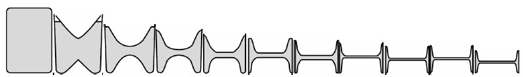
Figure 5.5: Typical roll-pass sequences used in producing structural I-Beam shape

Figure 5.6: Typical roll-pass sequences used in producing structural 90 degree angle shape
The arrangement of rolls at a rolling station is called a rolling mill. The common types include: Two high (pull over/reversing), Three high, Four high, Continuous, Planetary, and Universal mills.
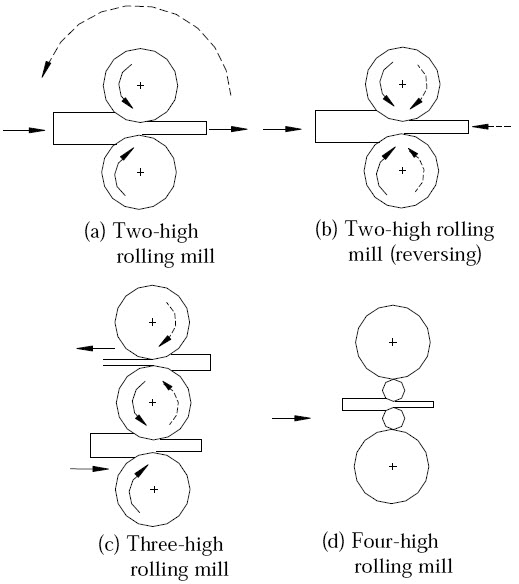
Figure 5.7: Different types of rolling mills
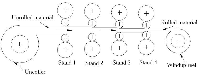
Figure 5.8: Continuous rolling mill with four rolling mill stands
5.4.5 Continuous Rolling Mill: Also known as tandem mill. High production using multiple stands. Velocities must be synchronized across stands as strip velocity increases with each reduction.
5.4.6 Planetary Rolling Mill: Reduces slabs to coiled hot rolled strips in a single pass. Pair of heavy backing rolls surrounded by small planetary rolls equi-spaced on its periphery. Rolls revolve like planets around the sun. Action is similar to forging. Feed rolls introduce slab; planishing rolls improve finish.
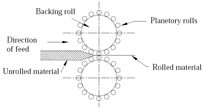
Figure 5.9: Planetary rolling mill
5.4.7 Universal rolling mill: Consists of horizontal rolls for rolling and vertical rolls for providing a perfect edge. Used for beams, I-sections, and plates requiring finished edges.
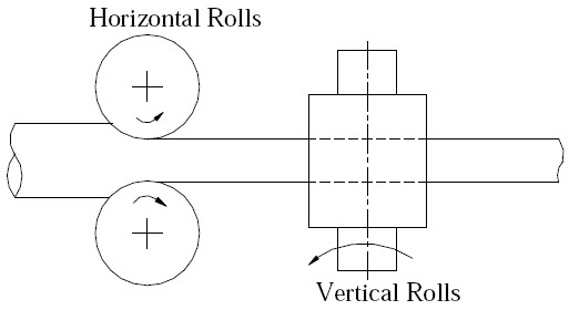
Figure 5.10: Universal rolling mill
5.5 Rolling Parameters
Let $l_1, b_1, t_1$ be initial and $l_2, b_2, t_2$ be final dimensions.
- Absolute draught (Draft): $\delta_t = t_1 - t_2$
- Maximum draft: $\delta_{max} = \mu^2R$ (where $\mu$ is friction coefficient, $R$ is roll radius)
- Absolute elongation: $\delta_1 = l_2 - l_1$
- Absolute spread: $\delta_b = b_2 - b_1$
- Elongation coefficient: Ratio of final length to initial length ($l_2/l_1$).
- Angle of contact (α): Angle subtended at center by contact arc.
- Coefficient of friction: $\mu = \tan \alpha$.
$\delta_{max} = (0.09)^2 \times 350 = 2.835$ mm.
For hot rolling with $\mu = 0.5$:
$\delta_{max} = (0.5)^2 \times 350 = 87.5$ mm.
5.6 Thread Rolling
Cold working process where a cylindrical workpiece is rotated between hard dies with negative thread contours. Part is rolled between stationary and reciprocating dies. Highly versatile for simultaneous threading, knurling, or rolling right/left hand threads.
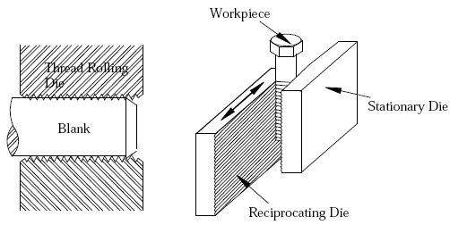
Figure 5.11: Thread rolling
5.7 Defects in Rolled Plates and Sheets
Defects can be surface (scale, rust, cracks) or internal. Caused by inclusions, impurities, or non-uniform deformation.
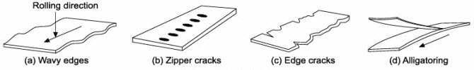
Figure 5.12: Defects in flat rolling
- Wavy edges: Due to roll bending where strip is thinner at edges.
- Zipper/Edge cracks: Due to poor ductility at rolling temperature.
- Alligatoring: Complex fracture due to non-uniform deformation or ingot defects.