Lesson 8: Special Casting Processes (Permanent)
📥 Lesson 8 Download8.1 Permanent Mould Casting Processes
Economic disadvantage of expendable mould casting is that a new mould is required for every casting. The basic difference between sand casting and permanent mould casting is the use of metal (or permanent) mould, that is, the mould is not destroyed as in case of sand casting process and the same mould can be reused many times after cleaning for producing another casting.
The processes include:
- Basic permanent mould casting (Gravity Die Casting)
- Pressure Die casting
- Centrifugal casting.
8.2 Basic Permanent Mould Casting Process (also known as Gravity Die Casting)
In permanent mould casting process, permanent moulds are used and the castings are made by pouring molten metal into the mould under the force of gravity. The process is normally used for cast iron and, occasionally, for a nonferrous casting. The permanent moulds are made from highly refractory materials (due to the very high pouring temperatures) or metal (steel or cast iron)and given a refractory coating. The mould is provided with fins on its outer surface for efficient air-cooling. The inner surface of the mould cavity is sprayed with an oil-carbon-silica mixture before each pouring. Typically, permanent moulds constructed of two parts, similar to cope and drag as in case of sand casting and designed for easy, precise opening and closing. Permanent mould castings usually have better mechanical properties than sand castings because solidification is more rapid. Permanent mould casting process ensures product of good quality, uniform mechanical properties and better surface finish. Metal moulds usually are made of high-alloy iron or steel and have a production life of up to 1,20,000 or more castings. Typical products made by this process includekitchenware, automobile pistons, pump bodies, and certain castings for aircraft and missiles. A typical permanent mould is shown in Figure 1 (a-d).
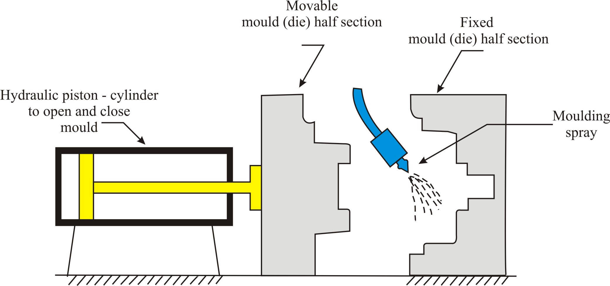 (a) permanent two piece mould is preheated and coated with silicon spray
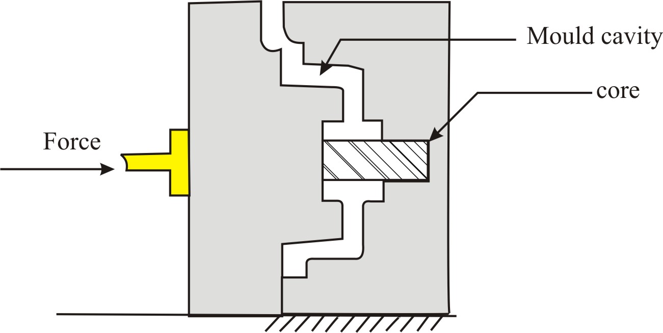 (b) cores (if used) are inserted and mould is closed
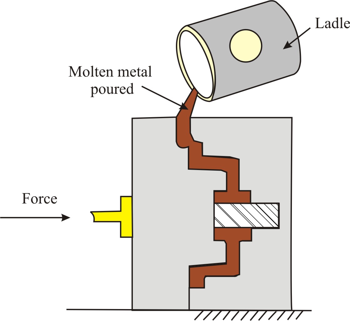 (c) molten metal is poured into the mould, where it solidifies
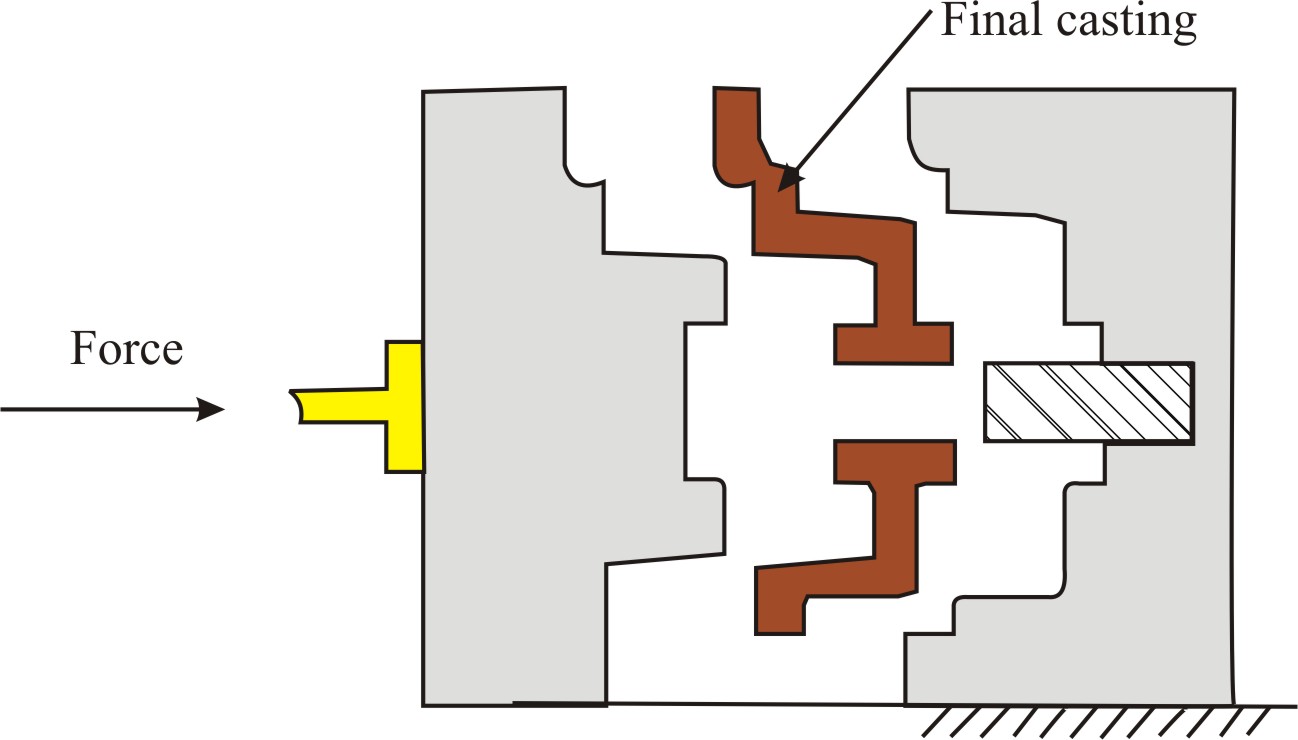 (d) Movable mould half section is moved back and the casting is obtained
8.2.1 Steps involved in Permanent Mould Casting Process
- The mould is preheated to 120-250oC and a refractory wash or mould coating is brushed or sprayed onto those surfaces of that will be in direct contact with the molten metal alloy.
- Cores, if required, are inserted, and the mould is closed.
- The molten metal alloy is poured into the mould through the gating system.
- The casting is allowed to solidify, after solidification, the mould is opened and cores and other loose mould members are withdrawn and the casting is removed from the mould.
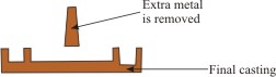
- The conventional foundry practice is followed for trimming of gates and risers from the castings.
8.2.2 Advantages of Permanent Mould Casting Process
- More rapid solidification caused by the cold metal mould results in castings finer grain structure, so castings with better strength.
- Cast surfaces in permanent mould casting are generally smoother with better surface finish than sand castings and closer dimensional tolerances can be maintained. Eliminating some secondary finishing or polishing operations.
- They do not ordinarily contain entrapped gases because no gasses are evolved (as in case of sand castings).
- This process can be automated.
8.2.3 Limitations of Permanent Mould Casting Process
- Generally limited to metals of lower melting point.
- Simpler part geometries compared to sand casting because of need to open the mould.
- High cost of mould process is best suited to high volume production.
8.3 Die-Casting Process
Die-casting is the process of making castings by using permanent moulds called die. (You should not confuse the term die used here with the die used in forging, extrusion and drawing processes.) This process is used for casting a low melting temperature material, e.g., aluminium and zinc alloys. The die used for diecastingsis very much similar to mould. Designed to hold and accurately close two mould halves and keep them closed while liquid metal is forced into cavity. Die-casting is similar to permanent mould casting except that the metal is injected into the mould under high pressure of 10-210 MPa instead being fed bygravity. Pressure is maintained during solidification, then mould is opened and part is removed. Use of high pressure to force metal into die cavity is what distinguishes this from other permanent mould processes. This result in a more uniform structure, good surface finish and good dimensional accuracy. For manyparts, post-machining can be totally eliminated, or very light machining may be required to bring dimensions to size. The process, when applied to a plastic casting, is called injection moulding.
Die casting process can be classified into two types viz.
- Hot chamber die-casting process, and
- Cold chamber die-casting process
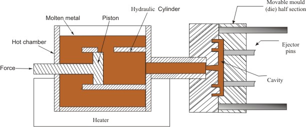
8.3.1 Hot Chamber Die-Casting Process
The hot chamber die-casting process is shown in Figure 2 . When the piston is in the extreme left position, molten material in the hot chamber around the cylinder fills the cylinder (Figure 2 (a)).
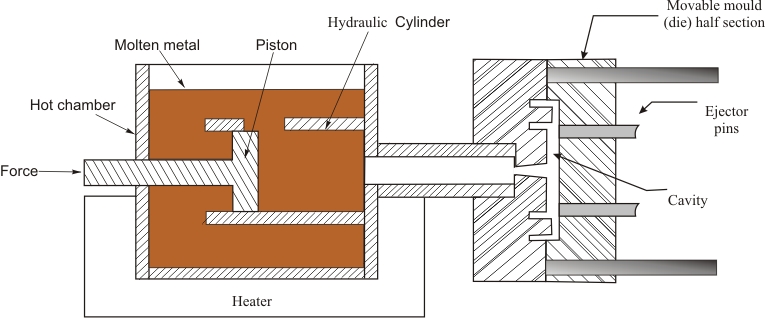
(a) Cycle in hot-chamber casting - with die closed and plunger withdrawn, molten metal flows into the cylinder
(b) Cycle in hot-chamber pressure die casting - piston forces metal in cylinder to flow into die (mould), maintaining pressure during cooling and solidification
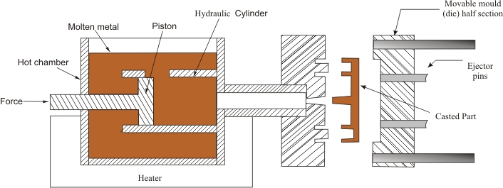
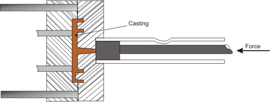
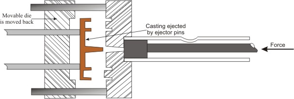
(c) Cycle in hot chamber pressure die casting - piston is withdrawn back, movable die slides forward, casted product is ejected out by ejector pins
Figure 2: Hot chamber Pressure Die-casting processAs the piston moves forward, the die cavity is filled under pressure (Figure 2 (b)). The metal is solidified quickly and casting is removed from the die. This is very fast process with up to 1000 cycles/hour are possible. The process is suitable for low melting temperature materials, i.e. zinc, tin, lead, and magnesium.
8.3.2 Cold chamber Die-Casting
The setup for cold chamber die-casting is shown in Figure 3. The process is very much similar to hot chamber die casting method. The molten material is fed into the cold cylinder chamber from where it is forced into the die cavity under pressure. Cold chamber die casting method is generally slower than hot chamber die casting method as pouring of molten metal is separate step.
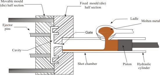
(a) Cycle in cold-chamber casting - with die (mould) closed and piston withdrawn, molten metal is poured into the chamber/ cylinder
(b) Cycle in cold-chamber casting - piston forces metal to flow into die (mould), maintaining pressure during cooling and solidification
Cold chamber die-casting differs from hot chamber die casting process in the following respects:
- Melting unit is not an integral part of the cold chamber die casting machine. Molten metal is brought and poured into the die-casting machine with the help of ladles (Figure3 (a)).
- Molten metal poured into the chamber of cold chamber die casting machine is at lower temperature as compared to hot chamber die casting machine.
- Pressure requirements in case of cold chamber die casting machine is higher than that of hot chamber die casting machine.
8.3.3 Advantages of Die Casting Process in general
- Economical for large production quantities
- Good accuracy and surface finish
- Thin sections are possible, as the liquid metal is forced into the die with high external pressure.
- Rapid cooling provides small grain size and good strength to casting
8.3.4 Disadvantages of Die Casting Process in general
- Generally limited to metals with low metal points
- Part geometry must allow removal from die
8.4 Centrifugal Casting Process
A family of casting processes in which the mould is rotated at high speed so centrifugal force distributes molten metal to outer regions of die cavity. When a body rotates about an axis a centrifugal force is created, this centrifugal force is used in getting the shape of the final casting. Typical centrifugal casting equipment is shown in Figure 8. In centrifugal casting, a permanent metal mouldrevolves at very high speeds in a horizontal, vertical or inclined position and the molten metal is poured. The poured molten metal is thrown on the walls of the mould cavity by centrifugal force. Centrifugal force is utilized to distribute liquid metal over the inner surfaces (walls) of the mould. The metal solidifies in the form of a hollow cylinder. Centrifugal castings can be made in almost any requiredlength, thickness and diameter. The cylinder wall thickness is controlled by the amount of liquid metal poured. The centrifugal force of this process keeps the casting hollow, eliminating the need for cores. Using centrifugal casting process it is possible to produce castings of good quality, dimensional accuracy and external surface detail. Typical examples of the products manufactured bythis process include pipes, gun barrels, bushings, flywheel, pressure vessels.
1. For producing a hollow part, the axis of rotation is placed at the centre of the desired casting.
2. The speed of rotation is maintained high so as to produce a centripetal acceleration of the order of 60g to 15g.
3. The centrifuge action segregates the less dense nonmetallic inclusions near the centre of rotation. It should be noted that the casting of hollow parts needs no core in this process.
4. Solid parts can also be cast by this process by placing the entire mould cavity on one side of the axis of rotation.
8.4.1 Advantages of Centrifugal Casting Process
- The castings, produced by this method, are very dense.
- By having several mould cavities, more than one casting can be made simultaneously.
- Hollow sections can be obtained without using Cores.
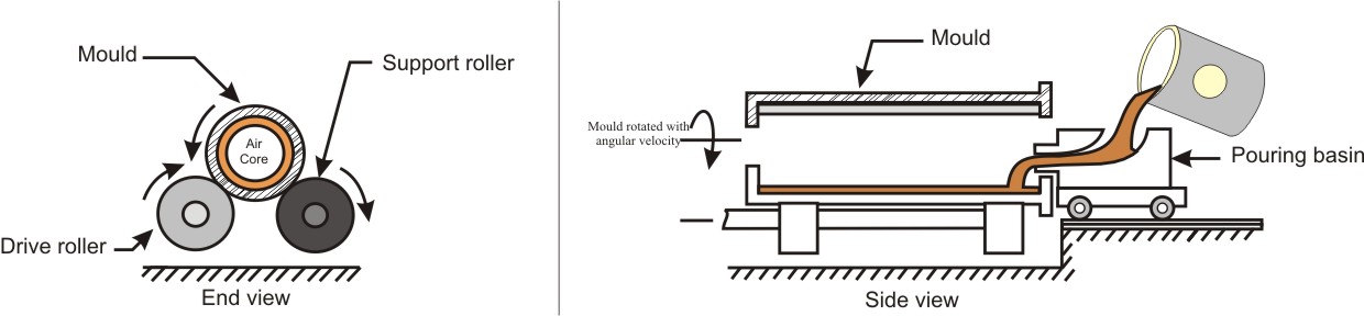
(a) Setup for Horizontal or True Centrifugal casting process
(b) Casted Pipe obtained from true centrifugal casting process (axi-symmetric and fully hollow)
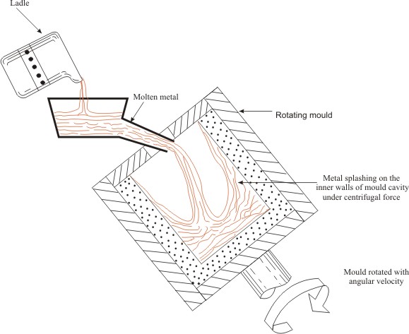
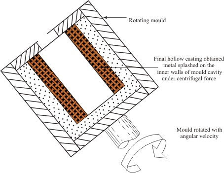
(c) Inclined Centrifugal Casting Process (i) Metal is being poured into the rotating mould and metal is getting slashed along the walls (ii) Metal solidified along the walls providing the hollow casting
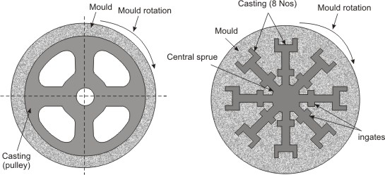
(d) Different shapes that can be obtained from various centrifugal casting process, (i) semi centrifugal casting process and (ii) Centrifuge Casting Process
Figure 4: Centrifugal casting processDepending on the method of feeding metal in to mould and location of mould with respect to axis of mould rotation, centrifugal casting process can be classified into following categories:
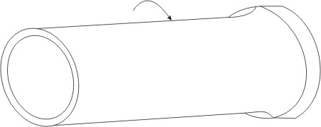
(i) True Centrifugal Casting (Figure 4 (a)) - The axis of rotation of the mould and that of the casting is same and horizontal. The casting produced is always centrally hollow and is made exclusively under the effect of centrifugal force.
Items produced by this process are: Cast iron pipes, tubes, bushings, rings.
(ii) Semi-Centrifugal Casting (Figure 4 (d-(i))) - The component cast is usually large and has rotational symmetry as in case of pulleys, flywheels, discs. Casting is done in a mould rotating about its vertical axis. The castings made by this method need not be centrally hollow.
Items produced by this process are: pulleys and wheels.
(iii) Centrifuge casting (Figure 4 (d (ii))) - In this case, the combined axis of rotation of the moulds (or the table carrying moulds) does not coincide with the axis of rotation of individual mould as the moulds are situated at a distance from the central axis of the mould table. In this process, a number of moulds areplaced around a vertical central sprue for feeding metal and are all connected to this central sprue. The table carrying moulds is rotated about the vertical axis of the sprue. The molten metal in the central sprue is fed to all the moulds under the effect of centrifugal force generated due to the rotation of the mould table. Theprocess of centrifuging or pressure casting is applied to the casting of nonsymmetrical objects such as brackets, bearing caps.
8.5 Slush Casting
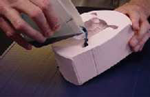
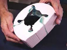
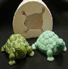
Slush Casting is a special type of permanent mould casting, where the molten metal is not allowed to completely solidify. A slush casting is produced by pouring the liquid material into an open-top permanent mould, after the desired wall thickness is obtained, the mould is inverted therefore, not yet solidified moltenmetal is drained out (Figure-5). This is useful for making shell-like ornamental objects from low melting point metals such as zinc, tin or lead alloys, for example, candlesticks, lamps, lamp base, toys, statues, masks. Low-meltingpoint metals such as lead, zinc, and tin are used. The exterior appearance isimportant, but the strength and interior geometry of the casting are minor considerations.
8.6 Continuous Casting
Continuous casting process can be used for producing castings of large length with a uniform cross-section. In this process continuous pouring of molten metal into a horizontal or vertical mould (pouring die) opened at both ends, cooling it there rapidly till metal solidifies and removing the solidified product in acontinuous form from the other end of the mould (Figure 6). Cooling jacket are made, sometimes, integral with the furnace. It also incorporates an integrated valve to stop the metal flow into the mould when desired. The molten metal flows into the mould from below the metal surface so that impurities are not included init. As it flows down it is cooled rapidly by quick dissipation of heat by the circulating water in the jacket around the metal mould. Withdrawing rolls below the mould help in pulling down the solidified casting at a controlled speed. A saw is fitted to cut the casting into desired lengths. The shapes that can be producedby this process include square, rectangular, hexagonal etc. The process is used now-a-days to produce blooms, billets, slabs and tubings of very long lengths directly from molten metal in steel plants replacing the traditional casting of ingots in separate moulds and later convert them into blooms or billets. The process ofcontinuous casting is largely used for casting steel, brass, copper, bronze, aluminium, grey cast iron and alloy cast iron.
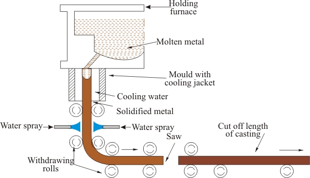 Figure 6: Continuous Casting Process
Summary of casting processes
| Process | Advantages | Limitations |
|---|---|---|
| Sand | Almost any metal can be cast; no limit to part size, shape, or weight; low tooling cost. | Some finishing required; relatively coarse surface finish; wide tolerances. |
| Shell mould | Good dimensional accuracy and surface finish; high production rate. | Part size limited; expensive pattern and equipment. |
| Evaporative pattern | Most metal can be cast, with no limit to size; complex part shapes. | Patterns have low strength and can be costly for low quantities |
| Plaster mould | Intricate part shapes; good dimensional accuracy and surface finish; low porosity. | Limited to non-ferrous metals; limited part size and volume for production; mould making time relatively long. |
| Ceramic mould | Intricate part shapes; close tolerance parts; good surface finish. | Limited part size. |
| Investment | Intricate part shapes; excellent surface finish; almost any metal can be cast. | Part size limited; expensive pattern, moulds and labour. |
| Permanent mould | Good surface finish and; dimensional accuracy; low porosity; high production rate. | High mould cost; limited part shape and complexity; not suitable for high melting point metals. |
| Die | Excellent dimensional accuracy and surface finish; high production rate. | High die cost; limited part size; generally limited to non-ferrous metals; long lead time. |
| Centrifugal | Large cylindrical or tubular parts with good quality; high production rate. | Expensive equipments; limited part shape. |