Virtual Labs IIT Roorkee
Electrical Measurement Laboratory
Measurement of High Resistance Using Loss of Charge Method
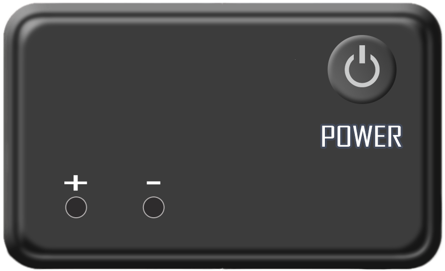
DC POWER SUPPLY
STEP 1 : Make Connections as per the instructions given below:
1. P1 of Power supply - P3 of Circuit Diagram
2. P2 of Power supply - P4 of Circuit Diagram
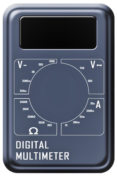
3. M1 of Multimeter - M3 of Circuit Diagram
4. M2 of Multimeter - M4 of Circuit Diagram
NOTE : If wire is wrongly connected, Click on node number to detach the wire.
STEP 2 : Click on "CHECK" Button for checking the connections.
STEP 3 : Turn ON Power supply by clicking on the Power button and set the voltage to 30V.
STEP 4 : Turn ON Switch 1 for charging the capacitor.
STEP 5 : Now, Turn ON Switch 2 for discharging the capacitor.
STEP 6 : Click on "START" Button to start the Timer & readings will add to the table automatically until the timer stops.
STEP 7 : Click on "PLOT" Button to plot the graph.
STEP 8 : Click on "PRINT" Button to print the webpage.
STEP 9 : Click on "RESET" Button to refresh the webpage.
FORMULA
1. Find R (High Resistance)
`R` = `(0.434t)/(Clog(V/v))` , C = 330µF
Where, V = Maximum Charging Voltage(30V)v = Discharging Voltage
OBSERVATION TABLE
| S.No. | Time (Sec) | Voltage (v) | log(V/v) | R (MΩ) |
|---|