INTRODUCTION TO PROGRAMMABLE LOGIC CONTROLLER AND INTRODUCTION TO DIGITAL I/O INTERFACE TO PLC
Objective:
To understand the basic working of Programmable Logic Controller (PLC) by taking a simple program.
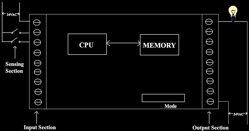
Block diagram of Programmable Logic Controller
STEP
1

Create a program (ladder diagram) to turn on the lamp only when both the switches are closed (And operation).
I1 I2 O1
This ladder diagram represents an And operation
| Truth table | |||
| I1 | I2 | O1 | |
| 0 | 0 | 0 | |
| 1 | 0 | 0 | |
| 0 | 1 | 0 | |
| 1 | 1 | 1 | |
STEP
2
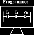

Download the program (ladder diagram) developed into PLC's memory using PROGRAMMER.
- Handheld programmer, PC or industrial computer programming terminal can be used as the PROGRAMMER
- The processor must be switched to program mode before downloading the program into PLC's memory
- In program mode, all outputs from the PLC are forced OFF regardless of their rung logic status, and the ladder I/O scan sequence is halted
Program mode
Downloading...
HALTED (Forced off)
STEP
3
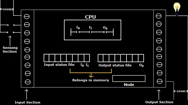


After downloading the program, put the PLC into RUN mode to solve the programmed instructions.
- In RUN mode, the program will continuously run and solve the programmed instructions
- The process of solving the programmed instruction is sometimes called as solving the logic. This constant running of the program in a PLC is called scanning
- Or, in other words, in RUN mode, the user program is executed. Input devices are monitored and output devices are energized accordingly
RUN mode...
0
0
0
OFF
OFF
OFF
0
0
0
OFF

© 2020 - SOLVE - The Virtual Lab @ NITK Surathkal