Geo-resistivity test for Groundwater level identification
Objective:
Determination of ground water level by using georesistivity method.
Apparatus used:
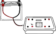
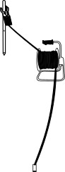
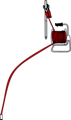
Resistivity meter, cables, battery, hammer, measuring tape etc.


Description
Georesistivity Test: The electrical resistivity test is useful for studying the existence of subsurface structures by observing the differences in their resistance to electrical current flow and hence determining the presence of groundwater.
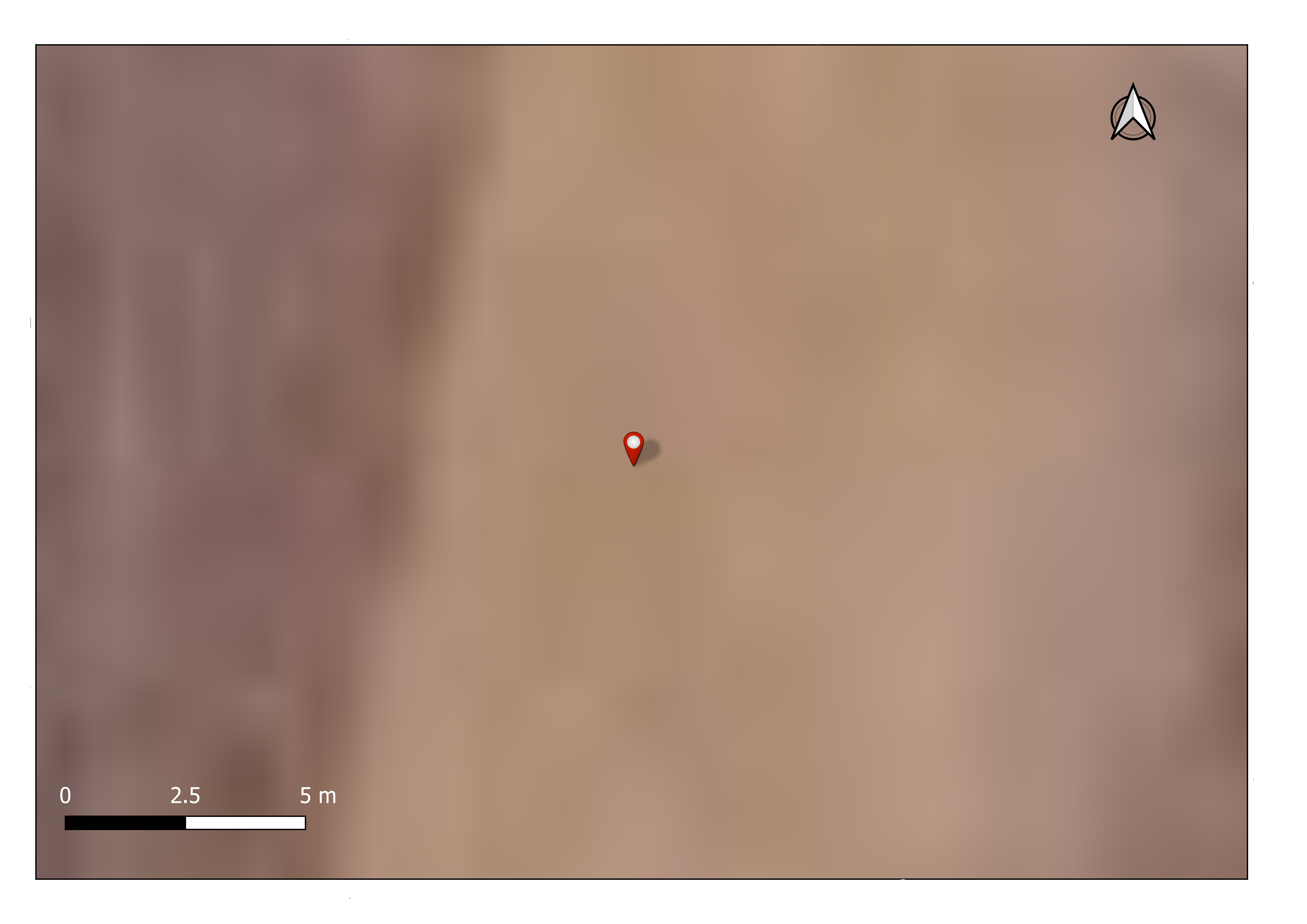
To conduct the geo-resistivity survey for the determination of ground water level in the selected location.
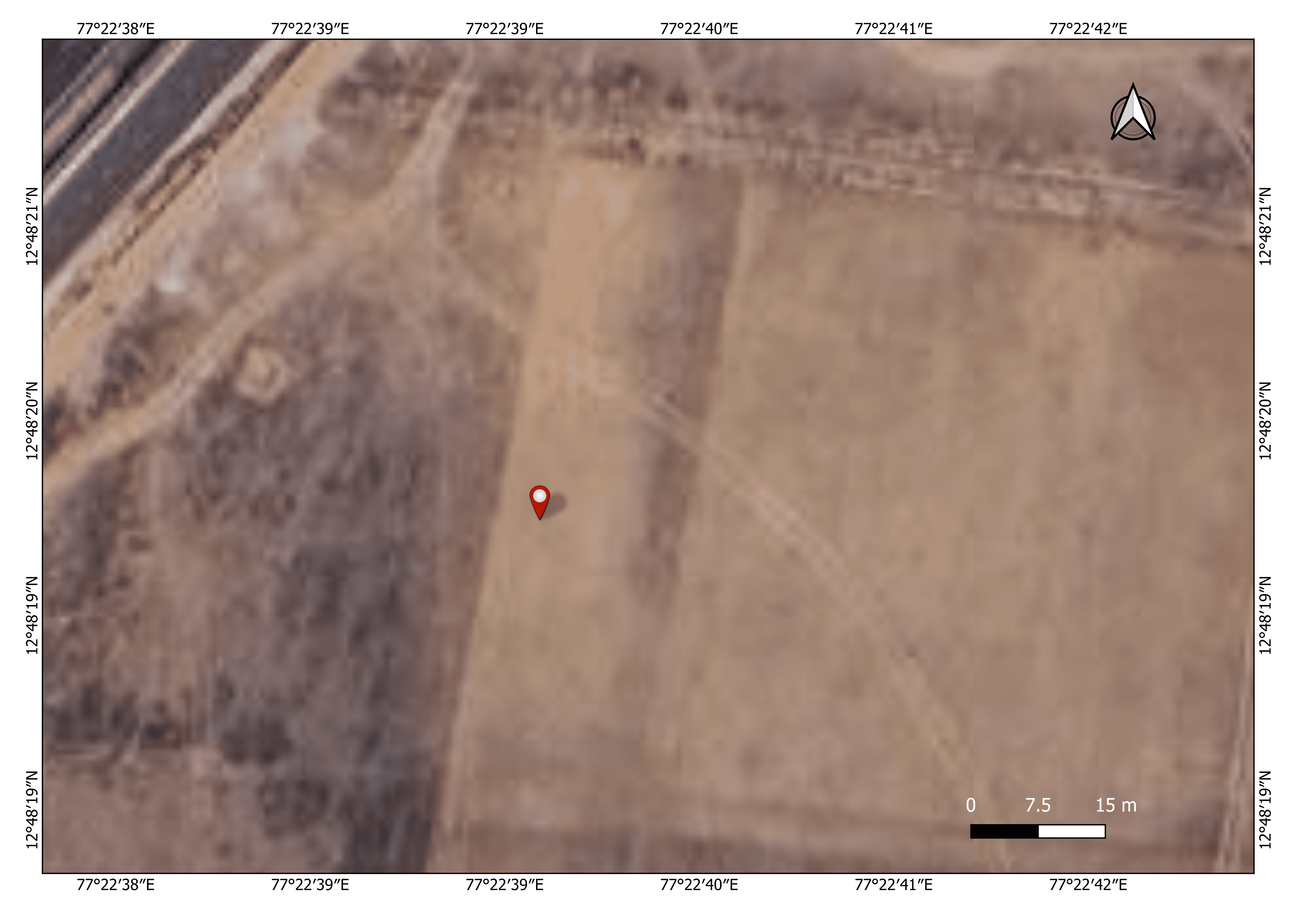
12°48'3.37"N 76°22'47.08"E
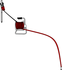
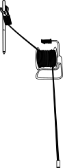
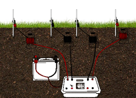
Measure the distance of 20 m and then place the electrodes.


Start point
End point

Hit on the current and potential electrodes using hammer and then connect the resistivity meter to the electrodes and record the resistivity values.


<---0.5m--->
<--------------------------1 m------------------------>


16.800
Hover on each dot to know the distance between electrodes.
STEP 4Continue the survey by changing the spacing of the electrodes.
77°22'39"E
77°22'40"E
12°48'20"N
12°48'20"N
77°22'40"E
77°22'39"E
12°48'20"N
12°48'20"N

1
2
3
4
5
6
7
8
9
10
11
12
13
14
15
16
17
18
19
20
21
22
23
24
25
26
27
28
<-0.5m->
<-------------------1 m----------------->
<-0.5m->
<-------------------3 m----------------->
<-0.5m->
<-------------------7 m----------------->
<-0.5m->
<----------------10 m------------------>
<--2m-->
<----------------10 m------------------>
<--2m-->
<----------------20 m------------------>
<--2m-->
<----------------30 m------------------>
<--5m-->
<----------------30 m------------------>
<--5m-->
<----------------40 m------------------>
<--5m-->
<----------------50m------------------>
<--5m-->
<----------------60m------------------>
<--5m-->
<----------------70 m------------------>
<--5m-->
<----------------80 m------------------>
<--5m-->
<----------------90 m------------------>
<--5m-->
<----------------100m------------------>
<--10m->
<----------------100m------------------>
<--10m->
<----------------110m------------------>
<--10m->
<----------------120m------------------>
<--10m->
<----------------130m------------------>
<--10m->
<----------------140m------------------>
<--10m->
<----------------150m------------------>
<--20m->
<----------------150m------------------>
<--20m->
<----------------170m------------------>
<--20m->
<----------------190m------------------>
<--20m->
<----------------210m------------------>
<--20m->
<----------------230m------------------>
<--20m->
<----------------250m------------------>
<--20m->
<----------------270m------------------>
<-0.5m->
<----------------1 m------------------>
Calculate the apparent resistivity of the soil using the readings from each location.
Variables Used in Calculations
L= The distance between the current electrodes (AB)
b= The distance between the potential electrodes (MN)
Resistivity= Value from the resistivity meter
K= Hydraulic conductivity
K = π*( (L2 )2- (b⁄2)2 (2*b2 ) )
Apparent Resistivity= K * Resistivity
| Sl.No | MN/2(m) | AB/2(m) | K | Resistivity(ohm-m) | Apparent resistivity |
|---|---|---|---|---|---|
| 1 | 0.5 | 1 | 2 | 16.800 | |
| 2 | 0.5 | 3 | 27 | 1.250 | |
| 3 | 0.5 | 7 | 153 | 1.650 | |
| 4 | 0.5 | 10 | 313 | 1.210 | |
| 5 | 2 | 10 | 75 | 1.680 | |
| 6 | 2 | 20 | 311 | 1.230 | |
| 7 | 2 | 30 | 703 | 0.937 | |
| 8 | 5 | 30 | 275 | 2.090 | |
| 9 | 5 | 40 | 495 | 1.590 | |
| 10 | 5 | 50 | 777 | 1.410 | |
| 11 | 5 | 60 | 1123 | 1.280 | |
| 12 | 5 | 70 | 1531 | 1.165 | |
| 13 | 5 | 80 | 2002 | 1.017 | |
| 14 | 5 | 90 | 2536 | 2.370 | |
| 15 | 5 | 100 | 3132 | 1.860 | |
| 16 | 10 | 100 | 1554 | 1.700 | |
| 17 | 10 | 110 | 1884 | 1.039 | |
| 18 | 10 | 120 | 2245 | 0.738 | |
| 19 | 10 | 130 | 2638 | 0.576 | |
| 20 | 10 | 140 | 3062 | 0.468 | |
| 21 | 10 | 150 | 3517 | 0.370 | |
| 22 | 20 | 150 | 1735 | 0.961 | |
| 23 | 20 | 170 | 2237 | 0.650 | |
| 24 | 20 | 190 | 2802 | 0.699 | |
| 25 | 20 | 210 | 3430 | 0.731 | |
| 26 | 20 | 230 | 4121 | 0.875 | |
| 27 | 20 | 250 | 4875 | 0.887 | |
| 28 | 20 | 270 | 5691 | 0.816 |
Plot the resistivity graph from the given data to locate the augment ground water.
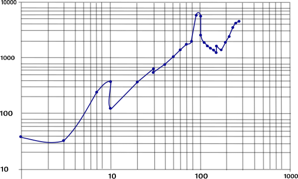
APPRES (ohm-m)
AB/2 (m)
Inference:
The study of Vertical Electrode Sounding indicates a few saturated fractures at deeper levels. These fractures are expected to get recharged from distant water bodies. The study of Vertical Electrode Sounding indicates the present study area is favorable location to augment ground water. There are two prominent fractures at the depth of 158.496m and 271.272m have been identified. As the study area is located on ridgs less scope for the recharged to the identified fractures. The expected yield is around 7570.823 lph.

