To familiarise with breadboard

  1. 1.Before performing the experiment, please read the manual carefully.

  2. 2.Read every slide and then click on next button given below for next slide.

  3. 3.For previous slide, click on previous button.


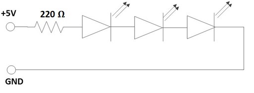
Series connections on Breadboard -


  1. Click on the Component button to place components on the table.
  2. Make connections as per the circuit diagram.
  3. Fig. 1 Circuit diagram for series connections of LEDs

  4. Click on Check Connections button. If connections are right, click on ‘OK’, then Simulation will become active.
  5. Observe output i.e. all LEDs will be ON.
  6. Now select Parallel connection.

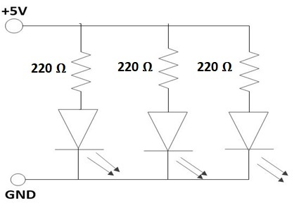
Parallel connections on Breadboard -


  1. Click on the Component button to place components on the table.
  2. Make connections as per the circuit diagram.
  3. Fig. 1 Circuit diagram for parallel connections of LEDs

  4. Click on Check Connections button. If connections are right, click on ‘OK’, then Simulation will become active.
  5. Observe output i.e. all LEDs will be ON.
  6. Click on ‘>’ button for next slide.


Familiarisation with Logic Gate connections of an IC 7432 -
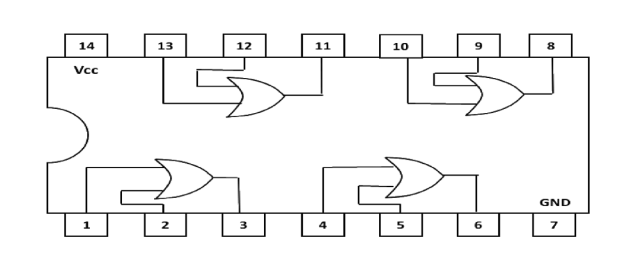

  1. Click on the 'Component' button to place components on the table.
  2. Connect pin 14 to the power supply (+5V) and pin 7 to ground (0V). (Refer pin diagram of IC 7432).
  3. Connect pin 1 and pin 2 to toggle switches A and B respectively.
  4. Connect corresponding output terminal (pin 3) to resistance (220 Ω). The other end of resistance is connected to positive (+) terminal of LED.
  5. Connect negative (–) terminal of the LED to ground.
  6. Fig. 1 Pin diagram of IC 7432

  7. Click on 'Check Connections' button. If connections are right, click on ‘OK’, then Simulation will become active.
  8. Apply different combinations (0,0); (0,1); (1,0) and (1,1) to input terminals of one gate (say pins 1 and 2) by using toggle switches A and B.
  9. Observe the corresponding output on the LED.
  10. Fill the observed values in the Truth Table.
  11. Verify the Truth Table of OR gate from the experimental results by clicking on 'Check' button, if outputs are correct then click on OK.
  12. Repeat steps 3 to 10 for different gates of the IC.

Truth table

A B A+B
0 0
0 1
1 0
1 1