Fracture Toughness of Ceramics

Material Testing laboratory

Simulation Area

Move the mouse pointer on the images to see the details

Machine Over View

Protective Enclosure Indenter Head Diamond Pyramid Indenter Optical Microscope Sample Stage Sample

Observations

Test Parameters

Strain Rate 0.05 s⁻¹
Load Rate 0.2 mN/s
Displacement Rate 10 nm/s
Thermal Drift ≤ 0.05 nm/s

Fracture Toughness Formula

KIC = 0.016 (E/H)1/2 P c3/2

Where,

  • KIC – fracture toughness (MPa√m)
  • E – elastic modulus (GPa)
  • H – hardness (GPa)
  • P – applied load (N)
  • c – crack length from indentation center to crack tip (m)
  • 0.016 – empirical calibration constant

Fracture Toughness Results

SEM Indentation Image

Material Properties Used for Calculation

Property Symbol Typical Value Used Unit
Elastic modulus E 500 GPa
Hardness H 25 GPa

Measured Crack Lengths & Calculated Toughness

KIC = 0.016 (E/H)1/2 · P / c3/2

Crack Crack length c (µm) c (m) KIC (MPa√m)
1585.8×10⁻⁵4.5
2606.0×10⁻⁵4.3
3595.9×10⁻⁵4.4
4595.9×10⁻⁵4.4

Final Fracture Toughness Result

Parameter Value
Average crack length cavg 59 µm
Mean fracture toughness KIC ≈ 4.4 MPa√m

Conclusion

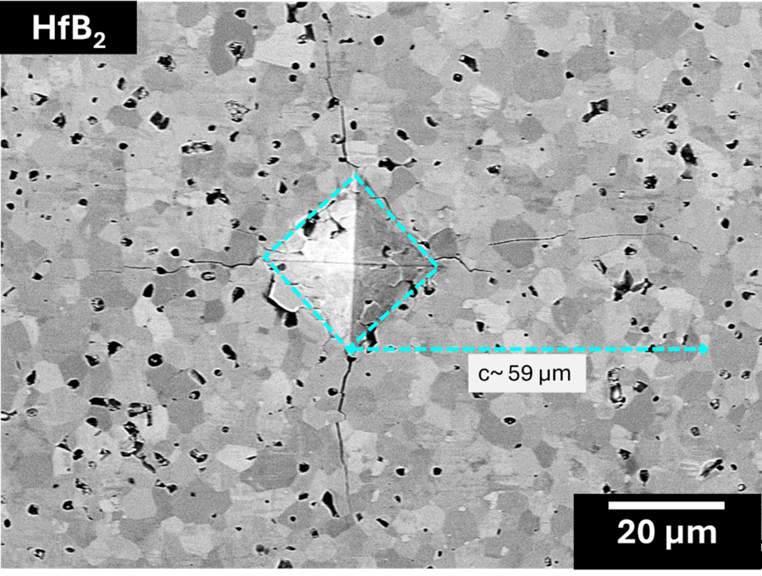
The Vickers indentation produced clear and symmetric radial–median cracks at the corners of each impression, allowing accurate crack-length measurement and reliable use of the Anstis equation.

Using the measured crack lengths (~58–60 µm) along with the elastic modulus and hardness of HfB₂, the average fracture toughness was calculated to be ≈ 4.4 MPa√m, matching expected dense ceramic behavior.

Since higher fracture toughness suppresses crack initiation and growth under contact loading, the measured KIC indicates improved resistance to microcracking and chipping, implying superior wear performance.

Crack Length Measurement

Measured Crack Lengths & Calculated Toughness

Crack Crack length c (µm) c (m) KIC (MPa√m)
1585.8×10⁻⁵4.5
2606.0×10⁻⁵4.3
3595.9×10⁻⁵4.4
4595.9×10⁻⁵4.4