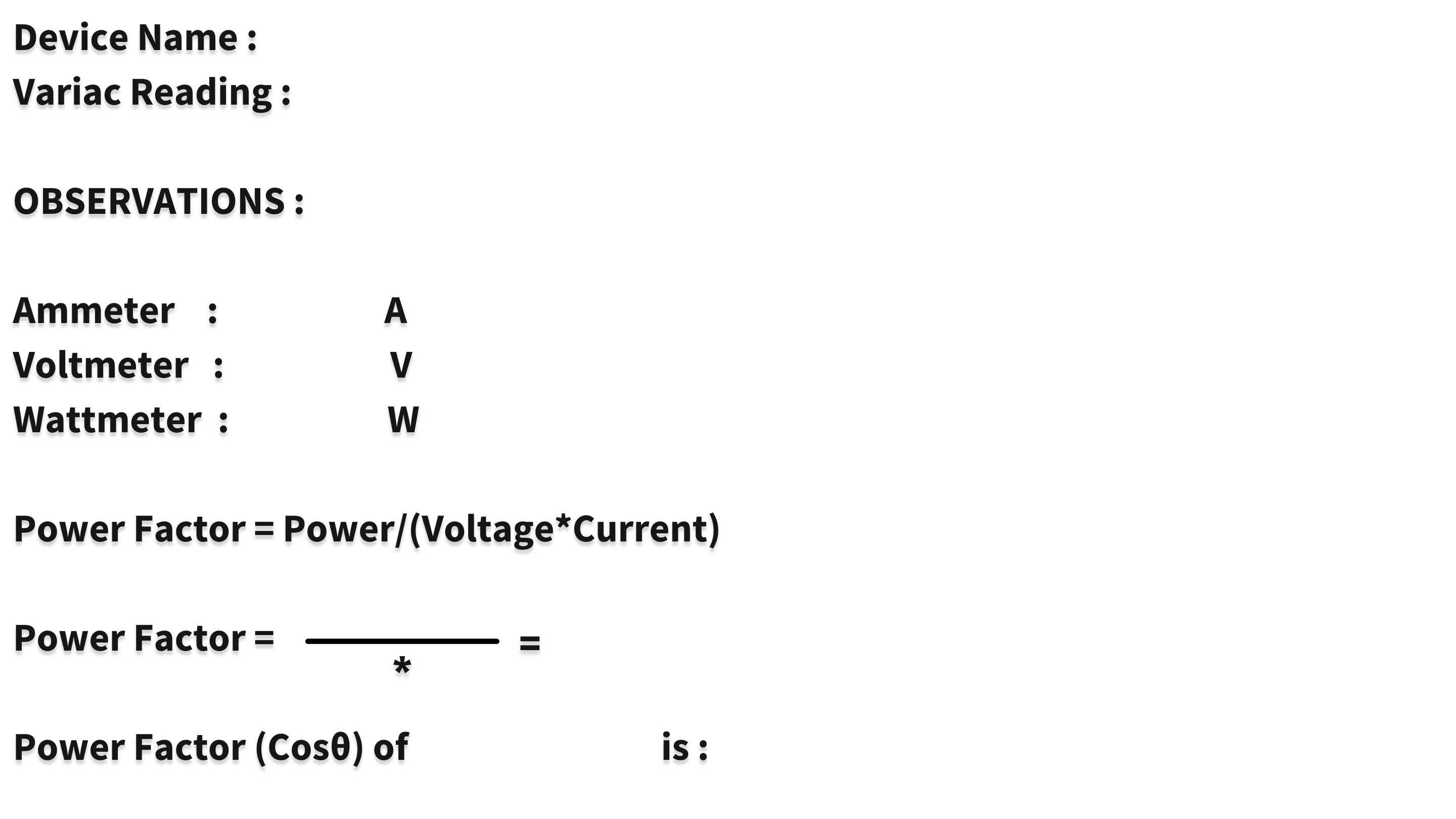
Study and Measurement of Power Factor of Electrical Load
Instructions
- STEP 1:Select a load by clicking on the ‘CHANGE LOAD’ button.
- STEP 2:Make connections as per the instructions given below :
(a) 1 to 11
(b) 2 to 12
(c) 3 to 13
(d) 4 to 14
(e) 13 to 15
(f) 16 to 17
(g) 5 to 18
(h) 6 to 9
(i) 9 to 10
(j) 8 to 19
(k) 7 to 20
(l) 7 to 14
- Note: Click on the label to delete the connection for the corresponding node.
- STEP 3:Then check the connections by clicking on the ‘CHECK’ button.
- STEP 4:If the alert is ‘Invalid connections’ then click on 'RESET' button and make connection again.
- STEP 5:If the alert is ‘Right connections’ follow the below steps.
- STEP 6:Turn ON the MCB.
- STEP 7:Then, switch on the variac by clicking on the button.
- STEP 8:Then, click on the variac knob to set the voltage at 230V.
- Note: Once, we have click on the variac knob it automatically set to 230 V. So we don't have to set it again.
- STEP 9:Then, click on switch to turn it ON.
- STEP 10:Click on ‘ADD’ button to add readings to the observation table.
- STEP 11:Click on ‘CALCULATE’ button to calculate the power factor of the load.
- STEP 12:Select a new load by clicking on the ‘CHANGE LOAD’button.
- STEP 13:Then,again check the connections by clicking on the ‘CHECK’ button.
- STEP 12:In calculation section, we have to manually find the power factor of the selected load by using the formulae and verify it with the help of ‘VERIFY’ button.
- STEP 13:Change the load and repeat the steps from 6 to 12.
- STEP 14:Click on ‘PRINT’ button to take out the print of the page.
- STEP 15: Click on the RESET button to reset the webpage.
Instructions
FORMULAS
= True Power/Apparent Power
= cos(Phase angle)
Note: L1:CFL, L2:Lamp, L3:LED, L4:Tubelight
OBSERVATION TABLE
| S.No. | Volts(V) | Amps(A) | Watts(W) | Power Factor |
|---|
EXPERIMENT

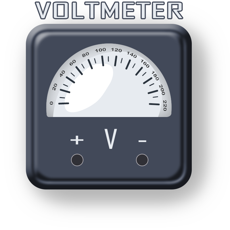

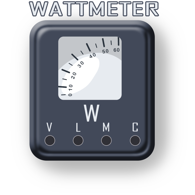


CALCULATIONS
