00:00
A B
A B
A B
A C
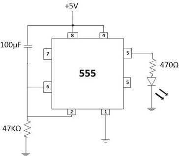
- Click on the components button to place the component.
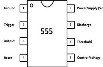
- Make connections as per the circuit diagram and pin diagram of IC.
- Click on 'Check Connections' button. If connections are right, click on ‘OK’, then Simulation will become active.
- Observe the Delay Time before the circuit turns on (LED glows).
- Compare it with the theoretical value.
- Click on the 'Reset' button to reset the page.