VLabs logo

Virtual Labs
IIT Kharagpur

IIT KGP Logo

Simulation


Instructions

    Find Tacho Generator Constant
  1. First connect the circuit diagram properly through the connecting dots (black dots) according to the instructions below.

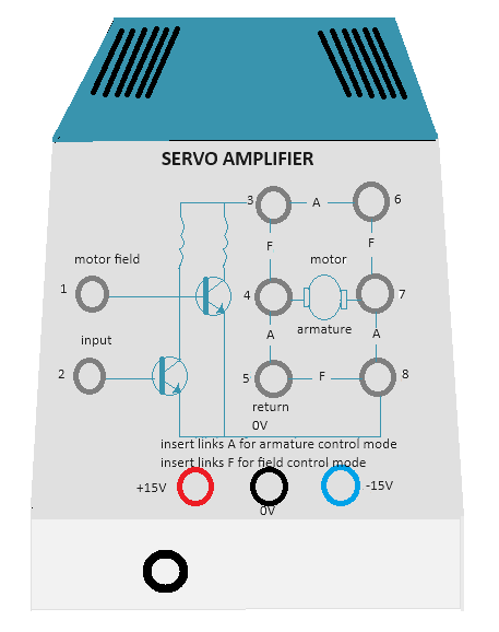
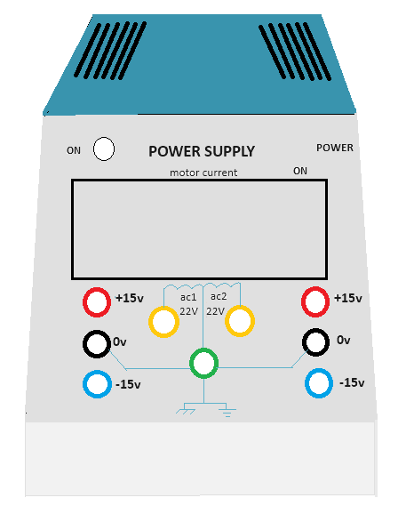
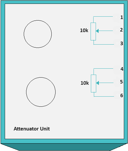
    Attenuator Unit upper potentiometer point 1 - Power Supply 0 V (left one), Attenuator Unit upper potentiometer point 3 - Power Supply +15 V (left one), Attenuator Unit upper potentiometer point 2 - Servo Amplifier point 1, Servo Amplifier point (3-6, 4-5, 7-8).

  2. Click on 'Check Connection' button to check whether the connection is proper or not. Click on the 'Power' switch in Power Supply box, the led will glow.

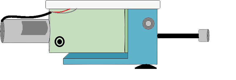
  3. Rotate the upper potentiometer knob in Attenuator Unit. Observe the tacho generator voltage in the black box above dc motor tacho unit plate. Rotate the knob untill the tacho generator voltage is about 1 V and motor starts rotating, observe the speed of the motor.

  4. Now click on 'Show Table' button to get the observation data. Check output around 2, 3, 4 and 5 volts of tacho generator following steps 3-4 and click on 'Show Table' button each time after increasing the voltage.

  5. Click on 'Plot' button to observe the plot 'Motor Speed (rpm) Vs. Tacho generator voltage (Volts)' and calculate the tacho generator constant (kg) from the slope in 'Motor Speed (rpm) Vs. Tacho generator voltage (Volts)' plot (explained in procedure section). Enter the value of kg in corresponding box beside observation table. Click on 'Download Plot' button to download the plot.

  6. Rotate the potentiometer knobs to its minimum value to stop the motor, switch off the power. Click on 'Clear' button


    Speed Control (Open Loop and Closed Loop)
  1. First connect the circuit diagram properly through the connecting dots (black dots) according to the instructions below.

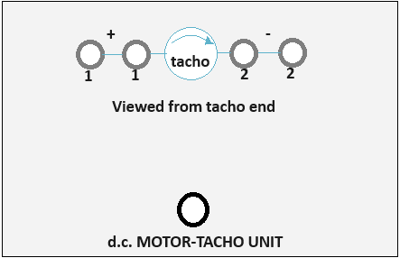
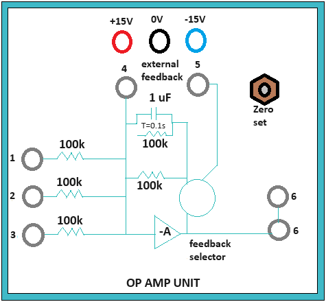
    Attenuator Unit lower potentiometer point 4 - Op Amp Unit 0 V, Attenuator Unit lower potentiometer point 5 - Op Amp Unit point 2, Attenuator Unit lower potentiometer point 6 - Op Amp Unit -15 V, Op Amp Unit point 6 (upper one) - Servo Amplifier point 1, Servo Amplifier point (3-6, 4-5, 7-8), Op Amp Unit +15 V - Power Supply +15 V (left one), Op Amp Unit -15 V - Power Supply -15 V (left one), Op Amp Unit 0 V - Power Supply 0 V (left one), DC motor tacho unit lower point - Power Supply 0 V, DC motor tacho unit lower point - DC motor tacho unit point 2 (first one).

  2. Click on 'Check Connection' button to check whether the connection is proper or not. Click on the 'Power' switch in Power Supply box ,the led will glow.

  3. Rotate the lower potentiometer knob in Attenuator Unit. Observe the reference voltage, error voltage and Speed. Rotate the knob untill the motor starts rotating at around 2000 rpm. Observe the tacho generator voltage in the black box above dc motor tacho unit plate. Click on 'Show Table' button to get the observation data.

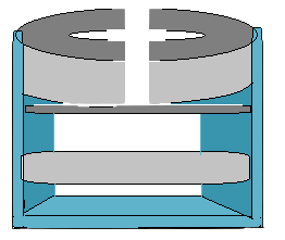
  4. Now click on the plus sign on 'Brake Change' to set the magnetic braking (loading) arrangement to point 2. Observe the change in speed and tacho generator voltage.

  5. Now click on 'Show Table' button to observe the observation table. Change brake position from 2-10 in step of 2 and check speed, tacho generator voltage following step 4 and click on 'Show Table' button each time after changing brake position.

  6. Now click on 'Plot' button to observe the plot 'Motor Speed (rpm) Vs. Braking Load (units)'. Click on 'Download Plot' button to download the plot.

  7. Rotate the potentiometer knobs to its minimum value to stop the motor, switch off the power. Click on 'Clear' button.

  8. Now make the circuit connection following step 1 and connect the velocity error feedback (Op Amp Unit point 3 - DC motor tacho unit point 1 (first one)) for closed loop control and follow steps 2-6 again.

  9. Click on 'Pre amplifier Characteristics' button to observe the characteristics of the pre amplifier , click on 'Position Control' button to perform the experiment of controlling the position of the motor rotor. To perform the experiment of controlling the speed of the motor click on 'Speed Control' button.


Tacho generator voltage (V) rpm
Brake Position
Reference voltage (V) Error Voltage (V)