COMPONENTS

DC Source
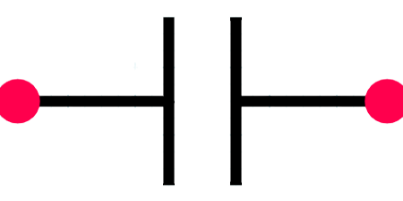
Capacitor

Mosfet N

Resistor
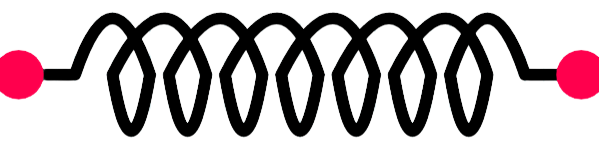
Inductor
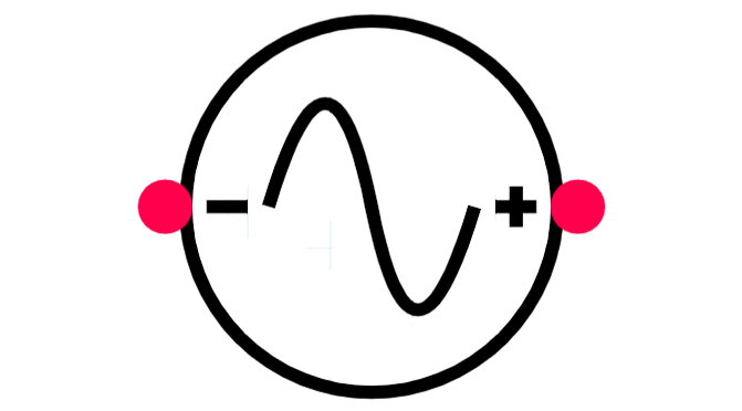
AC Source

Switch

Not Gate
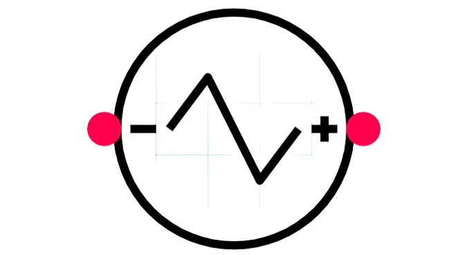
Triangle wave


Voltmeter
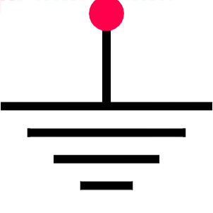
Ground
OBSERVATION TABLE
| S.No. | VLrms (V) |
VLavg (V) |
|---|
3
4
C1
6
5
7
M1
9
8
10
M2
23
24
R
1
2
DC
20
21
VM1
11
GND1
22
GND2
25
26
VLOAD
12
13
C2
15
14
16
M3
18
17
19
M4
27
28
L
31
32
S1
29
30
VM2
33
34
S2
35
36
G
37
GND3
38
39
VSINE
40
41
42
COMP
43
44
VTRI
46
47
SINE
48
49
TRI
45
GND4
50
GND5
WAVEFORM
- STEP 1: Drag and drop the components in the workspace to create the circuit.
- Nos of required components:
- DC Source – 1, Capacitor - 2, Mosfet N – 4, Resistor - 1,
- Inductor – 1, AC Source – 1, Switch – 2, Not Gate- 1,
- Triangle wave – 1, Comparator -1, Voltmeter – 5, Ground – 5
- STEP 2: Make the connections as per the instructions given below:
- (a) (01-03, 03-06, 06-09, 02-13, 13-16)
- (b) (16-19, 04-11, 11-12, 07-15, 10-18)
- (c) (07-23, 20-23, 21-22, 23-25)
- (d) (24-27, 26-28, 18-28, 28-29)
- (e) (30-37, 05-31, 17-31, 14-33)
- (f) (08-33, 32-35, 41-47, 42-48)
- (g) (34-40, 36-40, 39-47, 38-45)
- (h) (48-43, 44-50, 46-45, 49-50)
- Note: Click on the wire to delete the connection.
- STEP 3: Click on the CHECK button to check the connections.
- Note: Right click on the component to open the dialog box to edit the properties of the component.
- STEP 4: Input the values for all the required components (DC Source, AC Source, Triangle Source, Capacitors, Resistor and Inductor) and the waveform will get plot automatically.
- STEP 5: Now, Click on the ADD button to insert the reading into the observation table.
- STEP 6: Now, you can input different values as per your requirement to get the desired waveform.
- STEP 7: Repeat Step 5 to again insert the reading into the table and now repeat Steps 6 to 7 to take more readings.
- STEP 8: Click on the PRINT button to take out the print of the webpage.
- STEP 9: Click on the RESET button to reload the webpage.
