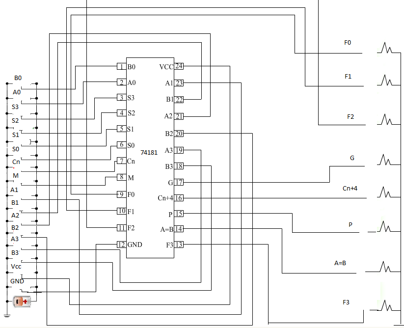
Design of Arithmetic Logic Unit
INSTRUCTION
- Apply high voltage to M(mode control input) and low volatge to \(C_{n}\).
- Apply \(V_{CC}\) and low level voltage to ground(GND).
- Then apply low voltage to all the 4 select inputs (\(S_{3}\) \(S_{2}\) \(S_{1}\) \(S_{0}\)). Logical operation will be performed. The output will be inverted A.
- Next, apply high voltage to \(S_{0}\) and apply low voltage to all other select inputs(\(S_{3}\) \(S_{2}\) \(S_{1}\)). Logical operation will be performed. The output will be A + B.
- Now apply high voltage to\(S_{1}\) and low voltage to all other select inputs(\(S_{3}\) \(S_{2}\) \(S_{0}\)). Logical operation will be performed. The output will be AB.
- To check the outputs for arithmetic operations, apply high voltage to \(C_{n}\) and low volatge to M. Then apply low voltage to all the 4 select inputs(\(S_{3}\) \(S_{2}\) \(S_{1}\) \(S_{0}\)). Arithemetic operation will be performed.The output will be A
- Apply high voltage to \(S_{0}\) and apply low voltage to all other select inputs(\(S_{3}\) \(S_{2}\) \(S_{1}\)). Arithmetic operation will be performed. The output will be A + B.
- For Arithmetic operation A+ B, apply high voltage to \(S_{1}\) and low voltage to all other select inputs(\(S_{3}\) \(S_{2}\) \(S_{0}\)).
- Apply all the combinations to all the select inputs(\(S_{3}\) \(S_{2}\) \(S_{1}\)) to check the Logical and Arithmetic operation output.
- Note: Red symbolize as Low (L), Green symbolize as High(H).
Connect Vcc
Please disconnect GND


