Virtual Labs IIT Roorkee
Electrical Measurements Laboratory
Anderson Bridge

MCB


POWER


X

SPEAKER

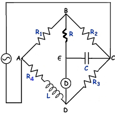
CIRCUIT DIAGRAM
1 KΩ
1 KΩ
1.5 KΩ
10 KΩ

COIL


Q


P


Y


STEP 1 : Make Connections as per the instructions given below:
1. M1 of MCB - P1 of Power & M2 of MCB - P2 of Power
2. OS1 of Oscillator - OS3 of Oscillator & OS2 of Oscillator - OS4 of Oscillator
3. S1 of Speaker - E of Circuit Diagram
4. S2 of Speaker - D of Circuit Diagram
5. COM - D of Circuit Diagram
6. L1 - Coil of Circuit Diagram
NOTE : If wire is wrongly connected, Click on node number to detach the wire.
STEP 2 : Click on "CHECK" Button for checking the connections.
STEP 3 : Click on the MCB to Turn ON the supply.
STEP 4 : Set Oscillator to maximum from dropdown.
STEP 5 : Select the values from various dropdown to get minimum frequency sound from speaker.
STEP 6 : Click on "ADD" button to add the readings to the Observation Table.
NOTE : If combination is wrong then select another combination & the balanced condition button becomes active after the wrong combination alert by clicking on the ADD button.
STEP 7 : Click on "PRINT" button to print the webpage.
STEP 8 : Click on "RESET" button to reset the webpage.
FORMULA
Find L (Unknown inductance)
L=CR3(R1+2R)
Where, C = Capacitance
R = P+Q+X+Y, Resistance range 10Ω to 1KΩ
OBSERVATION TABLE
| S.No. | C (µF) | R (KΩ) | R1 (KΩ) | R3 (KΩ) | L=CR3(R1+2R4) mH |
|---|