
Phase Shift Keying (PSK)
Theory:
PSK is a digital modulation scheme which is analogues to phase modulation. Binary Phase Shift Keying (BPSK) is the simplest form of PSK. In binary phase shift keying two output phases are possible for a single carrier frequency one out of phase represent logic 1 and logic 0. As the input digital binary signal change state the phase of output carrier shift two angles that are 180o out of phase. In a PSK modulator the carrier input signal is multiplied by the digital data. Each time a change in input logic condition will change the output phase consequently for PSK the output rate of change equal to the input rate range and widest output bandwidth occurs when the input binary data are alternating 1/0 sequence. The fundamental frequency of an alternate 1/0 bit sequence is equal to one half of the bit rate.
PSK Transmitter:
In PSK, binary ‘1’ is represented by the actual carrier, and binary 0 by the 180-degree phase shift of the carrier.
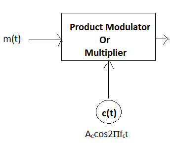
1 => S1(t) = Accos2Пfct
0 => S2(t) = Accos{2Пfct + 1800} = - Accos2Пfct
Here, the electric signaling scheme is NRZ
1 = +ve
0 = -ve
PSK Receiver:
For the demodulation of PSK, a soft detector (SD) will be used
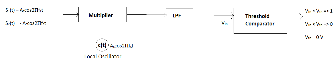
1 => Accos2Пfct.Accos2Пfct => (Ac)2/2 > Vth
0 => Accos2Пfct.(-Accos2Пfct) => -(Ac)2/2 < Vth
a. Constellation Diagram
Energy per bit (Eb):
** for Transmission of binary ‘1’
Eb = ∫0Tb(Ac.cos2П.fc.t)2 dt
= ∫0Tb((Ac)2/2) dt +
∫0Tb((Ac)2.cos4П.fc.t)/2) dt
= ∫0Tb((Ac)2/2) dt + 0 (area = 0 due to complete cycle)
= ((Ac)2/2).Tb
Ac = √(2Eb/Tb)
** for Transmission of binary ‘0’ Eb = ∫0Tb(-Ac.cos2П.fc.t)2 dt
= ∫0Tb((Ac)2/2) dt +
∫0Tb((Ac)2.cos4П.fc.t)/2) dt
= ∫0Tb((Ac)2/2) dt + 0 (area = 0 due to complete cycle)
= ((Ac)2/2).Tb
Ac = √(2Eb/Tb)
** Constellation Diagram
1 => S1(t) = Ac.cos2П.fc.t = √(2Eb/Tb).cos2Пfct = √(Eb).
√(2/Tb).cos2Пfct
0 => S2(t) = -Ac.cos2П.fc.t = -√(2Eb/Tb).cos2Пfct = -√(Eb).
√(2/Tb).cos2Пfct
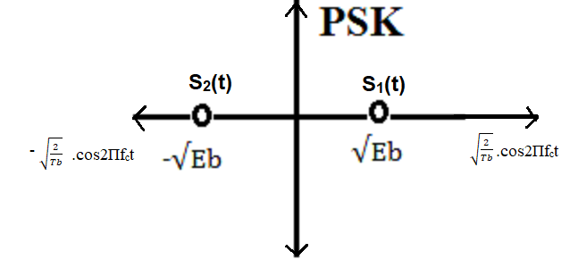
Figure: Constellation Diagrams of PSK
So, energy of S1(t) = (√(Eb))2 = Eb
So, energy of S2(t) = (-√(Eb))2 = Eb
Distance between the signaling points, d12 = 2(√(Eb))
High-order PSK (e.g., 8 PSK, 16 PSK) can transmit more bits per
symbol but is more sensitive to noise. Low-order PSK (e.g., BPSK,
QPSK) is less susceptible to noise.
PSK modulation can be visualized using a constellation diagram,
where each point represents a symbol. In the presence of noise,
points may be away from the original positions, making them harder
to distinguish.
b. Under different noise configurations
PSK Modulation with AWGN
In PSK modulation, digital data is represented by varying the phase
of the carrier signal. Binary PSK (BPSK) is a common form of PSK
modulation where the carrier phase is shifted by 180 degrees for
different binary symbols.
Mathematically, the PSK-modulated signal x(t) can be represented as:
x(t) = Accos2Пfct, { for binary symbol 1}
x(t) = Accos(2Пfct + 180), { for binary symbol 0}
Where:
fc is the carrier frequency.
Ac is the carrier amplitude.
In the presence of AWGN, the received signal y(t) becomes:
y(t) = x(t) + n(t)
Where:
x(t) is the PSK-modulated signal.
n(t) is the AWGN.
The AWGN introduces noise across all phases and amplitudes,
impacting the phase shifts of the PSK signal. Since PSK relies on
phase differences for symbol differentiation, the noise can cause
phase shifts, leading to errors in demodulation. The SNR
(signal-to-noise ratio) plays a crucial role in determining the
quality of demodulation.
PSK Modulation with Rayleigh Fading:
Rayleigh fading introduces random amplitude and phase variations to
the received signal due to multipath propagation. In the case of PSK
modulation, the mathematical representation of the received signal
(y(t) under Rayleigh fading is:
y(t) = h . x(t) + n(t)
Where:
h is the complex fading coefficient.
x(t) is the PSK-modulated signal.
n(t) is the noise.
The fading coefficient h introduces random variations in both
amplitude and phase to the signal components. These variations
affect the phases of the PSK signal, potentially leading to errors
in phase detection and symbol demodulation.
PSK modulation under different noise configurations involves adding
noise to the modulated signal. AWGN introduces phase and amplitude
noise across all phases, affecting PSK symbol differentiation.
Rayleigh fading introduces random amplitude and phase variations due
to multipath propagation, impacting the phase of the PSK signal. The
reliability of PSK demodulation depends on the SNR for AWGN and the
characteristics of the fading channel for Rayleigh fading.
c. Under Different Scenarios
Phase Shift Keying (PSK) is a modulation technique where the phase
of a carrier signal is varied to transmit digital information. The
performance of PSK modulation can vary in different scenarios based
on factors such as signal-to-noise ratio (SNR), noise, interference,
and channel conditions.
High SNR (Low Noise):
PSK modulation performs well in scenarios with high SNR and low
noise levels. The different phase shifts corresponding to binary
states can be accurately detected at the receiver, leading to
accurate data detection and low error rates.
Low SNR (High Noise):
PSK modulation is sensitive to phase changes, which can lead to
errors in low SNR scenarios due to noise-induced phase fluctuations.
In situations with low SNR and high noise, the receiver might
struggle to distinguish the correct phase shifts, leading to
increased error rates.
Modulation Index:
The choice of modulation index, which defines the phase separation
between different symbols, can impact PSK modulation's performance.
In some scenarios, a larger modulation index can lead to better
differentiation between phases, while in others, it might increase
susceptibility to phase noise.
Interference and Crosstalk:
PSK modulation can be affected by interference and crosstalk, which
can lead to phase shifts in the received signal. Interference can
cause phase ambiguity, resulting in errors in phase detection at the
receiver.
Frequency Selective Fading:
Similar to other modulation techniques, PSK modulation can
experience frequency-selective fading, which can distort the phase
of the received signal. Rapid phase changes due to fading can lead
to difficulties in accurate phase detection.
Channel Distortion:
Distortions introduced by the communication channel, such as phase
shifts or amplitude changes, can affect the received PSK signal.
These distortions can lead to errors in phase detection and,
consequently, data detection.
Coherent Detection:
Coherent detection of PSK modulation requires carrier
synchronization at the receiver. In scenarios where carrier
synchronization is challenging, phase errors can accumulate over
time, degrading the overall system performance.
Adaptive Modulation:
Adaptive modulation techniques can be employed with PSK to
dynamically adjust the modulation index or constellation size based
on channel conditions. This allows for optimization of data rate and
reliability according to the scenario.
Error Correction Coding:
Like other modulation techniques, adding error correction codes can
enhance PSK modulation's performance in noisy environments. These
codes provide redundancy, allowing the receiver to correct errors
caused by noise or phase fluctuations.
PSK modulation offers advantages in scenarios with favorable SNR and
can be sensitive to phase changes in noisy or interference-prone
environments. Its performance depends on factors like modulation
index, carrier synchronization, and the presence of noise or
distortion. Employing techniques such as error correction coding and
adaptive modulation can help optimize PSK modulation's performance
in various scenarios.