
Frequency Shift Keying (FSK)
Theory:
Frequency-shift keying (FSK) is a frequency modulation scheme in which digital information is transmitted through discrete frequency changes of a carrier wave. The simplest FSK is binary FSK (BFSK). BFSK uses a pair of discrete frequencies to transmit binary (0s and 1s) information. With this scheme, the "1" is called the mark frequency and the "0" is called the space frequency. If the incoming bit is 1, a signal with frequency f1 is sent for the duration of the bit. If the bit is 0, a signal with frequency f2 is sent for the duration of this bit. This is the basic principle behind FSK modulation. In the demodulator circuit, the FSK modulated signal is applied to a high Q tuned filter. This filter is tuned to the frequency of either 0 or 1. This filter passes the selected frequency and rejects the other.
FSK Transmitter:
In this binary 1 is represented by high frequency (say, f1) carrier and binary 0 by low frequency carrier (say, f2).
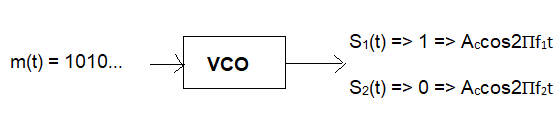
Here, the electrical signal representation technique is NRZ coding.
In which
1 = +ve
0 = -ve
VCO:
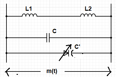
fi = 1 / (2П√((L1+L2)(C+C')) )
Transmission of binary ‘1’:
Here, the varactor diode is connected in reverse mode. And as C’ α
1/w, so, higher the width of the depletion layer, the lower the
capacitance C’. So, fi is high in this case.
On the other hand, as the width increases because reverse bias
increases the frequency fi increases. This frequency is termed ‘f1’.
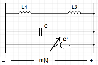
Transmission of binary ‘0’:

Here, the varactor diode is connected in forward mode. As it is connected in the forward mode so, the depletion region decreases. As the depletion region decreases, capacitance increases. So, fi decreases. This frequency is termed ‘f2’ and f1 > f2.
FSK Receiver:
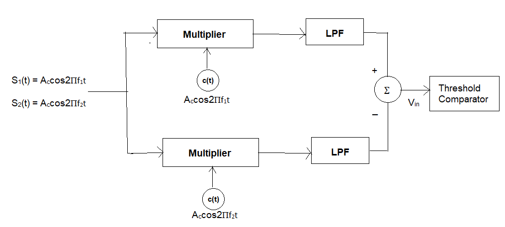
Here in the above figure, the threshold is 0 V. If the received
input signal in the upper half of the circuit is
Accos2Пf1t then, the output
before the threshold comparator will be
Accos2Пf1t.
Accos2Пf1t or
(Ac)2cos22Пf1t. In this case, the
average power will be (Ac)2 / 2 .
If the received input signal is
Accos2Пf2t, then the output
before the threshold comparator will be
Accos2Пf1t.
Accos2Пf2t. In this case, the
average power will be 0.
Similarly, for the lower half of the circuit, if the received input
signal is then, the output before the threshold comparator will be
Accos2Пf1t.Accos2Пf2t. In this
case, the average power will be 0. If the received input signal is
Accos2Пf2t , then the output
before the threshold comparator will be
Accos2Пf2t. Accos2Пf2t . In this
case, the average power will be
(Ac)2 / 2.
After summation in the above circuit, if the output is ((Ac)2 / 2) –
0 ) or (Ac)2 / 2, then the output will be binary ‘1’. On the other
hand, if the output is (-(Ac)2 / 2) – 0 ) or -(Ac)2 / 2, then the
output will be binary ‘0’.
a. Constellation Diagram
Energy per bit (Eb):
** for transmission of binary ‘1’
Eb = ∫0Tb(Ac.cos2П.f1.t)2 dt
= ∫0Tb((Ac)2/2) dt +
∫0Tb((Ac)2.cos4П.f1.t)/2) dt
= ∫0Tb((Ac)2/2) dt + 0 (area = 0 due to complete cycle)
= ((Ac)2/2).Tb
** for transmission of binary ‘0’
Eb = ∫0Tb(Ac.cos2П.f2.t)2 dt
= ∫0Tb((Ac)2/2) dt +
∫0Tb((Ac)2.cos4П.f2.t)/2) dt
= ∫0Tb((Ac)2/2) dt + 0 (area = 0 due to complete cycle)
= ((Ac)2/2).Tb
Ac = √(2Eb/Tb)
** Constellation Diagram
1 => S1(t) = Ac.cos2П.f1.t = √(2Eb/Tb).cos2Пf1t = √(Eb).
√(2/Tb).cos2Пf1t
0 => S2(t) = Ac.cos2П.f2.t = √(2Eb/Tb).cos2Пf2t = √(Eb).
√(2/Tb).cos2Пf2t
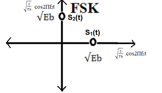
Figure: Constellation diagram of FSK
In the above figure values are in terms of the normalized functions.
√(2/Tb).cos2Пf1t and √(2/Tb).cos2Пf2t are orthogonal functions in
the interval (0, Tb). And the distance between signaling points, d12
= √(2Eb)
By interpreting these functions as vectors, the phase angle between
the resulting vectors will be 90 degrees.
High-order frequency shift keying (FSK) refers to using a larger
number of frequency shifts to present multiple symbols or bits of
digital data. In FSK, each frequency represents a unique symbol or
set of bits. High-order FSK schemes enable higher data rates but can
also be more susceptible to noise and channel impairments.
b. Under different noise configurations
FSK Modulation with AWGN
In FSK modulation, digital data is represented by varying the
frequency of the carrier signal. Let's consider a basic case of
binary FSK with two different carrier frequencies f1 and f2,
corresponding to the two binary symbols.
Mathematically, the FSK-modulated signal x(t) can be represented as:
x(t) = Accos2Пf1t, { for binary symbol 1}
x(t) = Accos2Пf2t, { for binary symbol 0}
In the presence of AWGN, the received signal y(t) becomes:
y(t) = x(t) + n(t)
Where:
x(t) is the FSK-modulated signal.
n(t) is the AWGN.
The AWGN introduces noise across all frequencies, affecting both the
amplitudes and phases of the signal components. Since FSK relies on
frequency differences for symbol differentiation, the noise can
cause frequency shifts and amplitude variations, leading to errors
in demodulation. The impact of noise can be quantified using the SNR
(signal-to-noise ratio).
FSK Modulation with Rayleigh Fading:
Rayleigh fading, as discussed previously, introduces random
amplitude and phase variations to the received signal due to
multipath propagation. In the case of FSK modulation, the
mathematical representation of the received signal y(t) under
Rayleigh fading is:
y(t) = h . x(t) + n(t)
Where:
h is the complex fading coefficient.
x(t) is the FSK-modulated signal.
n(t) is the noise.
The fading coefficient h introduces random variations in both
amplitude and phase to the signal components. As a result, the
amplitudes and phases of the two carrier frequencies can experience
fluctuations due to fading, potentially causing errors in symbol
detection.
FSK modulation under different noise configurations involves adding
noise to the modulated signal. AWGN introduces amplitude and phase
noise across all frequencies, affecting the differentiation between
FSK symbols. Rayleigh fading introduces random amplitude and phase
variations due to multipath propagation, impacting the signal's
components. In both cases, the reliability of FSK demodulation
depends on the SNR for AWGN and the characteristics of the fading
channel for Rayleigh fading.
c. Under Different Scenarios
Frequency Shift Keying (FSK) is a modulation technique where the
frequency of a carrier signal is varied to transmit digital
information. The performance of FSK modulation can vary in different
scenarios based on factors such as signal-to-noise ratio (SNR),
noise, interference, and channel conditions.
High SNR (Low Noise):
FSK modulation performs well in scenarios with high SNR and low
noise levels. The different frequency components corresponding to
binary states can be easily distinguished at the receiver, leading
to accurate data detection and low error rates.
Low SNR (High Noise):
FSK modulation is generally more robust against noise compared to
other modulation techniques like Amplitude Shift Keying (ASK). In
scenarios with low SNR and high noise, the receiver can still detect
the dominant frequency component, resulting in relatively lower
error rates compared to ASK.
Frequency Separation:
FSK modulation relies on having a sufficient frequency separation
between the carrier frequencies representing binary states. In
scenarios where the frequency separation is small, the likelihood of
error due to frequency overlaps or interference increases.
Interference and Crosstalk:
FSK modulation can be affected by interference from other signals or
crosstalk in shared communication channels. If the interfering
signal is close in frequency to one of the FSK carrier frequencies,
it might lead to errors in frequency detection at the receiver.
Frequency Selective Fading:
Similar to other modulation techniques, FSK modulation can
experience frequency-selective fading, where different frequency
components experience varying levels of attenuation. This can lead
to distortions in the received signal's frequency components,
affecting data detection.
Channel Bandwidth:
The channel bandwidth needs to accommodate the frequency separation
between the FSK carrier frequencies. In scenarios with limited
bandwidth, the choice of carrier frequency separation becomes
crucial to avoid overlap and distortion.
Coherent vs. Non-Coherent Detection:
FSK modulation can be detected coherently (using phase-locked loops)
or non-coherently (using frequency detectors). Coherent detection
offers better performance in terms of SNR but requires more complex
circuitry. Non-coherent detection is simpler but might have higher
error rates, especially in noisy environments.
Adaptive Modulation:
Adaptive modulation techniques can be applied to FSK modulation to
dynamically adjust the frequency separation based on channel
conditions. In favorable conditions, a larger frequency separation
can be used for higher data rates, while a smaller separation can be
chosen for reliability in challenging conditions.
Error Correction Coding:
Adding error correction codes to the FSK-modulated signal can
enhance its performance in noisy scenarios. The redundancy provided
by the codes helps the receiver detect and correct errors.
FSK modulation offers advantages in scenarios with varying levels of
noise and interference, making it a robust choice for certain
communication environments. Its performance depends on factors like
frequency separation, channel bandwidth, and the presence of
interference. Understanding these factors and potentially employing
techniques like adaptive modulation and error correction coding can
optimize FSK modulation's performance in various scenarios.