
Amplitude shift keying, Frequency Shift Keying, Binary Phase Shift Keying: Generation and Detection
Phase Shift Keying (PSK)
Theory:
Phase Shift Keying (PSK) is a digital modulation technique in which information is transmitted by changing the phase of a carrier signal. The simplest form, Binary PSK (BPSK), uses two phases: one phase for binary '1' and the opposite phase (180° shift) for binary '0'. Each change in input data directly shifts the phase of the carrier.
PSK Transmitter:
In BPSK:
\[ s(t) = \begin{cases} A_c \cos(2\pi f_c t), & \text{for binary 1} \\ A_c \cos(2\pi f_c t + \pi) = -A_c \cos(2\pi f_c t), & \text{for binary 0} \end{cases} \]
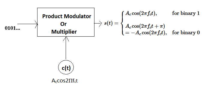
Fig 1: BPSK Transmitter
PSK Receiver:
BPSK can be demodulated using a coherent receiver. The received signal is multiplied by a locally generated carrier and integrated over the bit duration \(T_b\).
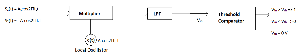
Fig 2: Coherent BPSK Receiver
In a coherent Binary Phase Shift Keying (BPSK) receiver, the incoming signal is first multiplied by a locally generated carrier signal that is synchronized in frequency and phase with the transmitter. This process is known as coherent detection. The multiplication shifts the signal to baseband, producing a component proportional to the transmitted data along with high-frequency terms.
The output of the multiplier is then passed through a Low-Pass Filter (LPF), which removes the high-frequency components and retains the baseband signal. The resulting signal is a positive or negative voltage level depending on whether a '1' or '0' was transmitted.
Finally, the filtered signal is fed into a threshold comparator. If the input voltage is greater than zero, the receiver decides that a binary '1' was transmitted. If the voltage is less than zero, it decides a binary '0'. This decision process converts the analog signal back into digital data.
Constellation Diagram of BPSK
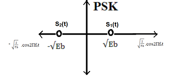
Fig 3: Constellation Diagram of BPSK
BPSK uses a single orthonormal basis function:
\[ \phi_1(t) = \sqrt{\frac{2}{T_b}} \cos(2\pi f_c t), \quad 0 \le t \le T_b \]
- Binary '1': \( s_1(t) = \sqrt{E_b} \, \phi_1(t) \)
- Binary '0': \( s_2(t) = -\sqrt{E_b} \, \phi_1(t) \)
Energy of both symbols: \( E_b \)
Distance between points: \( d_{12} = 2\sqrt{E_b} \)
The constellation lies on a single axis (in-phase), since BPSK only varies phase.
Effect of Noise
BPSK with AWGN:
The received signal:
\(
y(t) = s(t) + n(t)
\)
where \( n(t) \) is additive white Gaussian noise. Noise can cause phase shifts, leading to bit errors. Detection reliability depends on SNR.
BPSK with Rayleigh Fading:
The received signal:
\(
y(t) = h \cdot s(t) + n(t)
\)
where \( h \) is a complex fading coefficient. Fading introduces random amplitude and phase changes, affecting symbol detection. Robust demodulation requires considering channel variations and SNR.