
Amplitude shift keying, Frequency Shift Keying, Binary Phase Shift Keying: Generation and Detection
Frequency Shift Keying (FSK)
Theory:
Frequency Shift Keying (FSK) is a digital modulation technique in which information is transmitted by changing the frequency of a carrier signal. The simplest form is Binary FSK (BFSK), where two distinct frequencies are used.
Binary '1' is represented by a carrier of frequency \( f_1 \) (mark frequency), and binary '0' is represented by a carrier of frequency \( f_2 \) (space frequency). Each signal is transmitted for one bit duration \( T_b \).
FSK Transmitter:
In BFSK, the output signal is:
\[ s(t) = \begin{cases} A_c \cos(2\pi f_1 t), & \text{for binary 1} \\ A_c \cos(2\pi f_2 t), & \text{for binary 0} \end{cases} \]
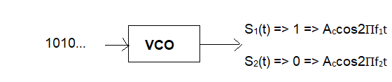
Fig 1: BFSK Transmitter
In a Binary Frequency Shift Keying (BFSK) transmitter, the digital input signal, consisting of binary bits (0s and 1s), is applied to a Voltage-Controlled Oscillator (VCO). The VCO generates a sinusoidal carrier signal whose frequency depends on the input bit value. When the input bit is '1', the VCO produces a carrier signal with frequency f1, represented as S1(t) = Ac cos(2πf1t). When the input bit is '0', the VCO switches to a different frequency f2, producing the signal S2(t) = Ac cos(2πf2t). The amplitude of the carrier remains constant in both cases, while only the frequency changes according to the input data. This variation in frequency allows the digital information to be transmitted over a communication channel.
Coherent FSK Receiver
A coherent (synchronous) binary FSK demodulator is called "coherent" because the mark and space frequencies are regenerated locally at the receiver. The incoming FSK signal is applied to two multipliers. One multiplier uses the locally generated mark frequency \( f_1 \), while the other uses the locally generated space frequency \( f_2 \). The outputs are then passed through low-pass filters (LPFs) to extract the baseband signal.
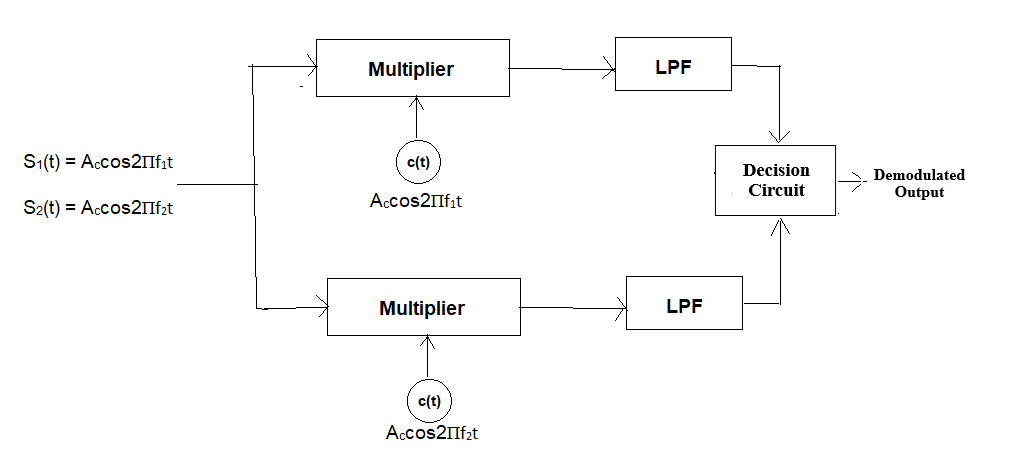
Fig 2: Coherent BFSK Receiver
FSK Signal Representation
At any instant, the received FSK signal can be represented as:
\( S_{1}(t) = A \cos(2\pi f_1 t) \) (for binary '1')
\( S_{2}(t) = A \cos(2\pi f_2 t) \) (for binary '0')
Where:
- \( A \) is the signal amplitude.
- \( f_1 \) is the mark frequency representing binary '1'.
- \( f_2 \) is the space frequency representing binary '0'.
- \( \Delta f = f_1 - f_2 \) is the frequency deviation.
Case 1: Binary '1' Transmitted
Multiplier 1 Output:
\( A \cos(2\pi f_1 t) \cdot A \cos(2\pi f_1 t) = \frac{A^2}{2} \left[ 1 + \cos(4\pi f_1 t) \right] \)
LPF 1 Output: \( \frac{A^2}{2} \)
Multiplier 2 Output:
\( A \cos(2\pi f_1 t) \cdot A \cos(2\pi f_2 t) = \frac{A^2}{2} \left[ \cos(2\pi(f_1 + f_2)t) + \cos(2\pi(f_1 - f_2)t) \right] \)
LPF 2 Output: 0 (since high-frequency terms are filtered out)
Decision: Output is binary '1' because LPF 1 > LPF 2.
Case 2: Binary '0' Transmitted
Multiplier 1 Output:
\( A \cos(2\pi f_2 t) \cdot A \cos(2\pi f_1 t) = \frac{A^2}{2} \left[ \cos(2\pi(f_1 + f_2)t) + \cos(2\pi(f_1 - f_2)t) \right] \)
LPF 1 Output: 0
Multiplier 2 Output:
\( A \cos(2\pi f_2 t) \cdot A \cos(2\pi f_2 t) = \frac{A^2}{2} \left[ 1 + \cos(4\pi f_2 t) \right] \)
LPF 2 Output: \( \frac{A^2}{2} \)
Decision: Output is binary '0' because LPF 2 > LPF 1.
Constellation Diagram of FSK
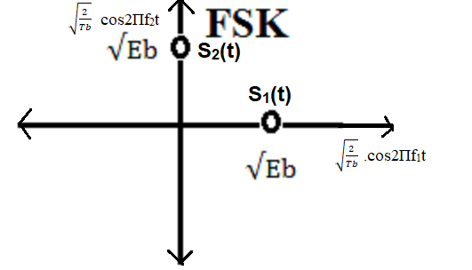
Fig 3: Constellation diagram of BFSK
BFSK signals are represented using two orthonormal basis functions, since two different frequencies are used:
\[ \phi_1(t) = \sqrt{\frac{2}{T_b}} \cos(2\pi f_1 t), \quad \phi_2(t) = \sqrt{\frac{2}{T_b}} \cos(2\pi f_2 t) \]
These basis functions are orthogonal over \( T_b \), meaning: \[ \int_0^{T_b} \phi_1(t)\phi_2(t)\,dt = 0 \]
- Binary '1': \( s_1(t) = \sqrt{E_b}\,\phi_1(t) \)
- Binary '0': \( s_2(t) = \sqrt{E_b}\,\phi_2(t) \)
The constellation points lie on two perpendicular axes. The distance between them is:
\[ d_{12} = \sqrt{(\sqrt{E_b})^2 + (\sqrt{E_b})^2} = \sqrt{2E_b} \]
This orthogonal structure improves noise performance compared to ASK.
Effect of Noise
AWGN Channel:
The received signal is:
\(
y(t) = x(t) + n(t)
\)
where \( n(t) \) is noise. Noise affects detection but BFSK is more robust than ASK since information is carried in frequency.
Rayleigh Fading:
The received signal is:
\(
y(t) = h \cdot x(t) + n(t)
\)
where \( h \) represents channel effects. This causes amplitude and phase variations, making detection more difficult.