
- Click on the components button and place all the component.
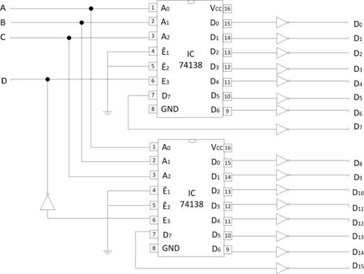
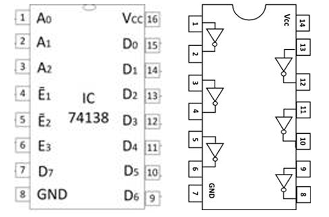
- Make connections as per the circuit diagram and pin diagram of ICs.
- Click on Check Connections button. If connections are right, click on ‘OK’, then Simulation will become active.
- Provide the input by clicking toggle switches A, B, C and D.
- Fill the observed values in the Truth Table.
- Verify Truth Table by clicking on Check button, if outputs are correct then click on OK.
Truth table
| A | B | C | D | Y |
|---|---|---|---|---|
| 0 | 0 | 0 | 0 | |
| 0 | 0 | 0 | 1 | |
| 0 | 0 | 1 | 0 | |
| 0 | 0 | 1 | 1 | |
| 0 | 1 | 0 | 0 | |
| 0 | 1 | 0 | 1 | |
| 0 | 1 | 1 | 0 | |
| 0 | 1 | 1 | 1 | |
| 1 | 0 | 0 | 0 | |
| 1 | 0 | 0 | 1 | |
| 1 | 0 | 1 | 0 | |
| 1 | 0 | 1 | 1 | |
| 1 | 1 | 0 | 0 | |
| 1 | 1 | 0 | 1 | |
| 1 | 1 | 1 | 0 | |
| 1 | 1 | 1 | 1 |